
From Engineering to Manufacturing
From BLDC Controller Prototype to Production-Ready Solution
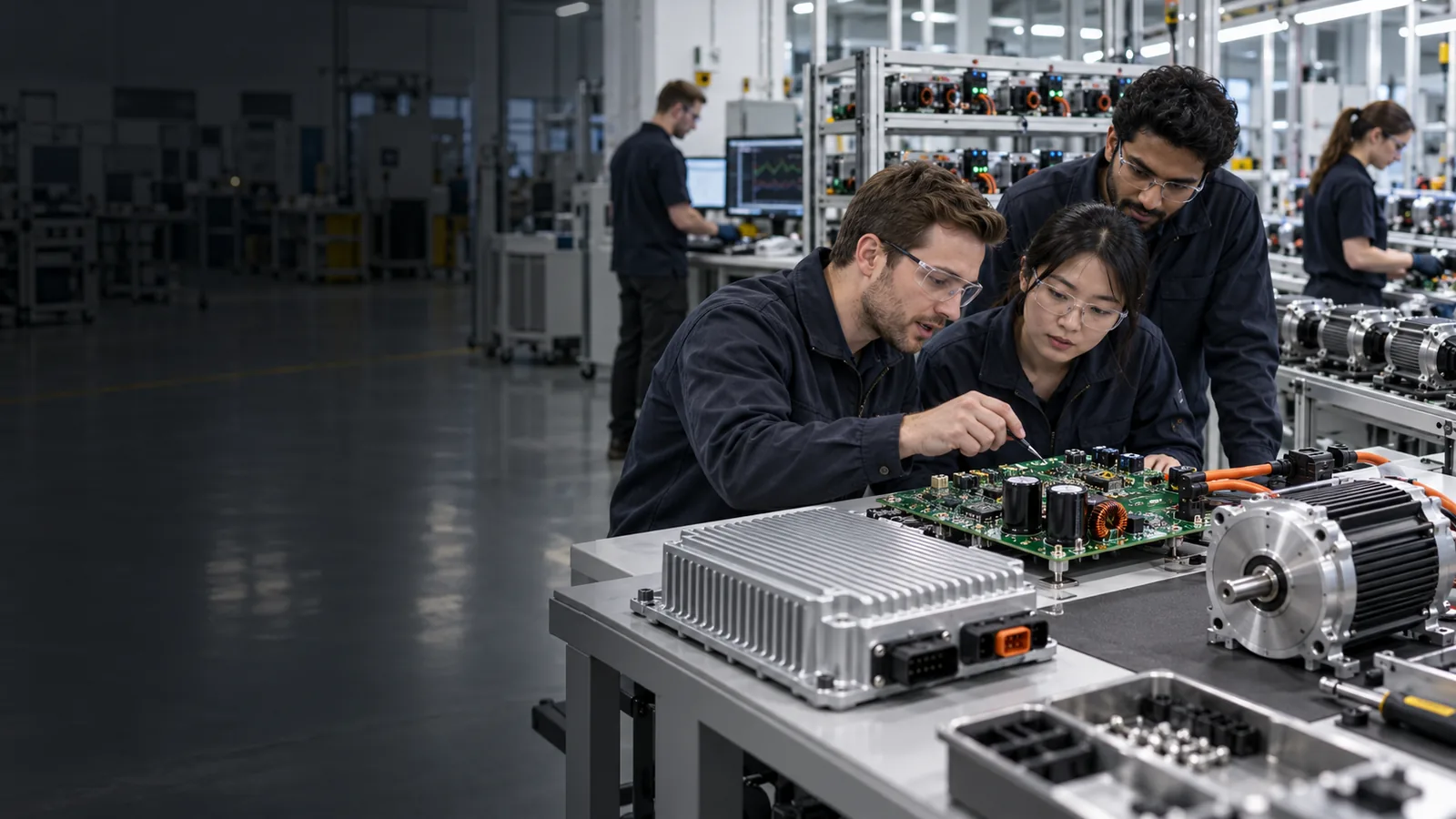
A controller project is not complete when the first prototype works. For OEM and ODM equipment manufacturers, the controller must also be repeatable, testable, manufacturable and suitable for integration into the final equipment.
Phase 1 · Requirements First
Production Success Starts Before the Prototype
A successful controller project begins with a clear understanding of the motor and final equipment. VIREOMOTOR first reviews the available technical information to determine what the controller actually needs to do.
Motor Information
Motor type, voltage, power, current, speed, torque requirements and motor datasheet.
Application Information
Axial fan, centrifugal fan, negative pressure fan, cooling fan, blower, water pump or other supported equipment.
Operating Requirements
Startup behavior, required speed, speed range, duty cycle, load characteristics and operating environment.
Control Requirements
Speed-control behavior, operating logic, equipment commands, protection and communication requirements.
Mechanical Requirements
PCB space, board dimensions, connector position, wiring and installation limitations where applicable.
Phase 2 · Engineering Prototype
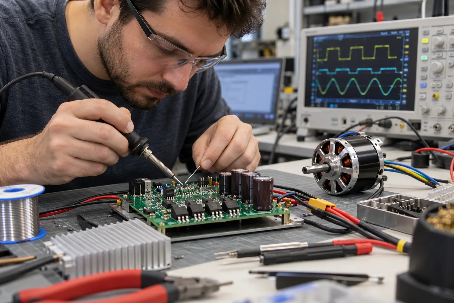
Build the Controller Around the Real Motor and Load
After the project requirements are understood, VIREOMOTOR evaluates whether an existing controller platform can be adapted or whether additional customization is required.
Existing Platform Evaluation
Where possible, evaluate a suitable existing controller platform first to reduce unnecessary redevelopment.
Hardware Configuration
Voltage, power stage, current capability, PCB structure, components, connectors and thermal considerations.
Software Configuration
Motor startup, speed regulation, operating logic, protection logic and application-specific functions.
Controller & Motor Matching
Evaluate Controller + Motor + Load rather than the board alone.
Phase 3 · Validation
A Prototype Must Work Inside the Actual Equipment
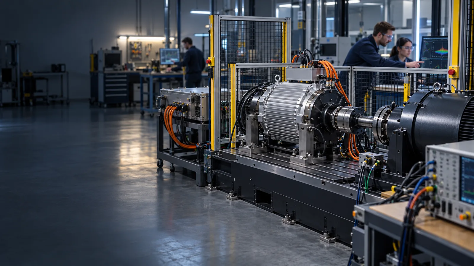
A controller that runs a motor successfully on a bench may still require further optimization before it is ready for production. Validation should answer whether the controller works in the application—not only whether the motor turns.
Startup, Running & Stop
Evaluate startup, running behavior, speed regulation, load response and stop behavior.
Real Load Conditions
Ventilation, cooling fan and pump applications can create different operating conditions.
Thermal Evaluation
Review controller heat generation, available cooling, installation environment and operating duration.
Application Behavior
Review operating functions against the real equipment behavior.
System Integration
Where applicable, evaluate controller interaction with the equipment's main control system.
Parameter Refinement
Refine controller parameters or functions based on application evaluation before design confirmation.
Phase 4 · Design Freeze
Turn a Working Prototype Into a Repeatable Product
Once controller performance has been evaluated and project requirements are confirmed, engineering flexibility must become a controlled production configuration.
Hardware Confirmation
PCB version, component configuration, power stage, connectors, wiring and structural requirements.
Software Confirmation
Confirm the intended software and control configuration.
Parameter Confirmation
Finalize project-specific motor-control parameters where applicable.
Technical Documentation
Transfer confirmed project information into the manufacturing process.
Production Requirements
Define product configuration, assembly, software, functional and testing requirements.
Change Control
Manage engineering changes carefully after the project enters production.
Phase 5 · Production Implementation
Engineering Requirements Carried Into Manufacturing
After design confirmation, the controller can move into controlled production. Select a production stage to review the manufacturing flow.
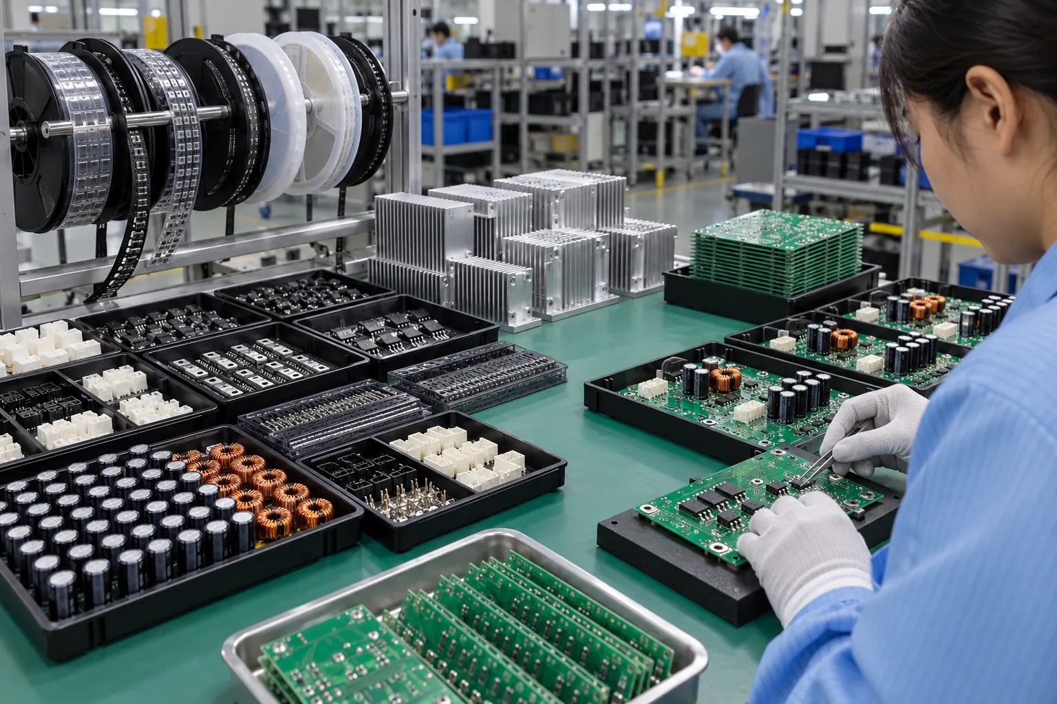
Component Preparation
Materials are prepared according to the confirmed product configuration. Production starts from the approved engineering definition rather than a generic bill of materials.
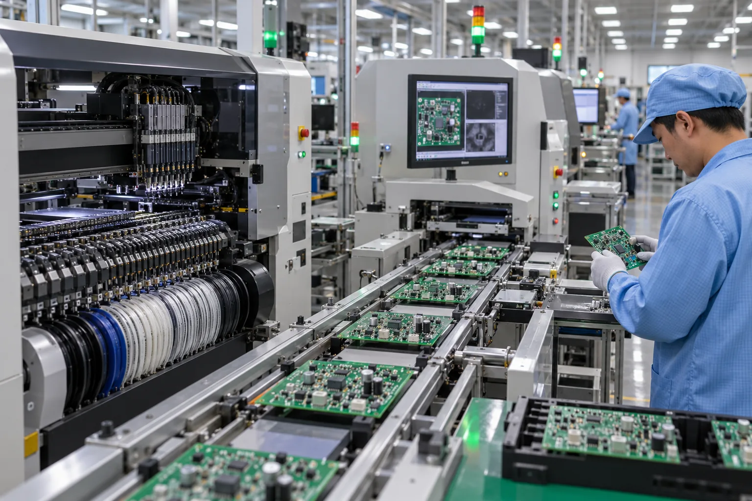
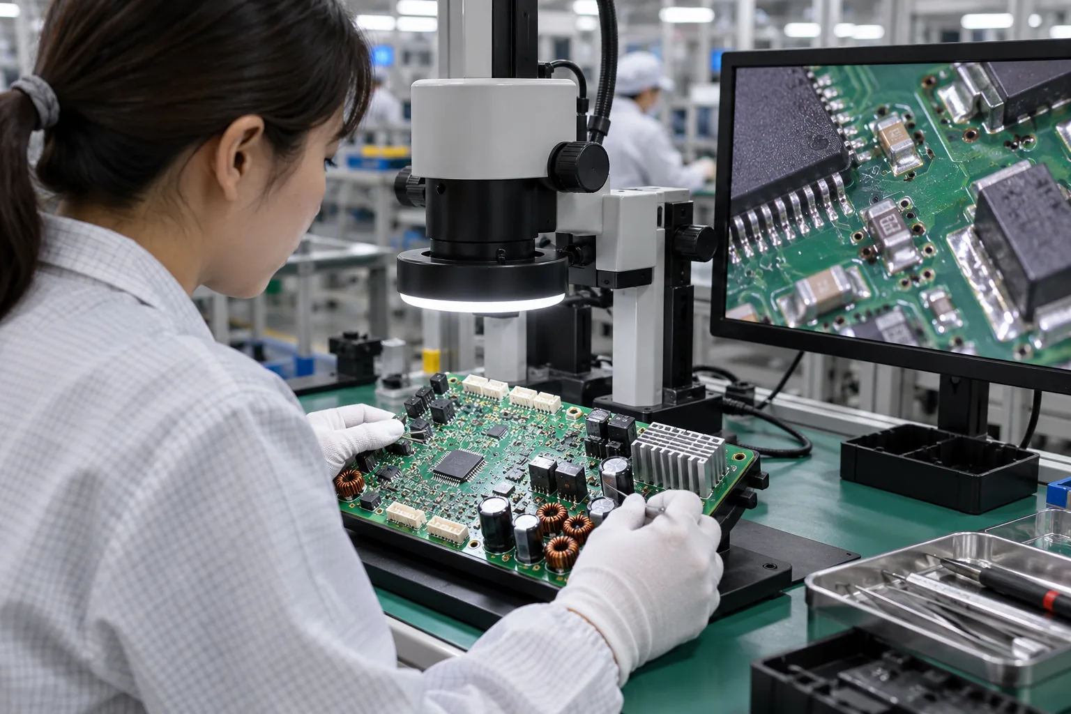
PCB Assembly
Electronic components are assembled according to the approved controller design. The goal is to reproduce the confirmed hardware configuration consistently.
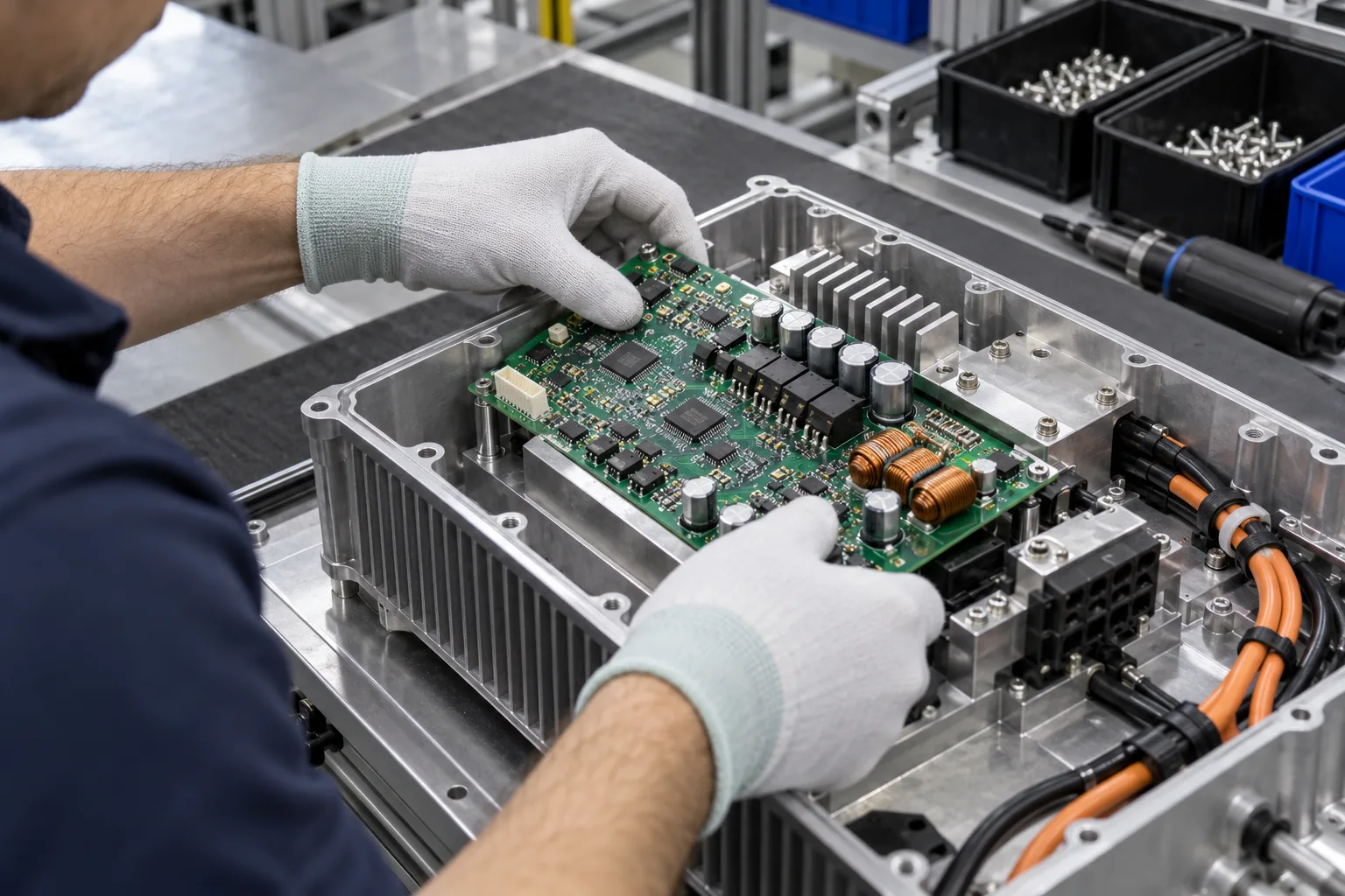
Controller Assembly
PCB, connectors and required components are integrated into the finished controller configuration.
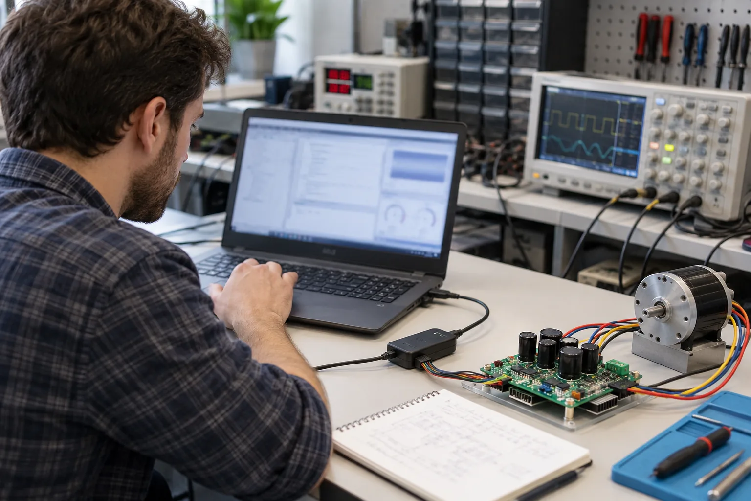
Software / Parameter Configuration
Where applicable, the confirmed software and project-specific parameters are applied to the controller configuration.
Functional Testing
The controller is checked against its intended operating functions.
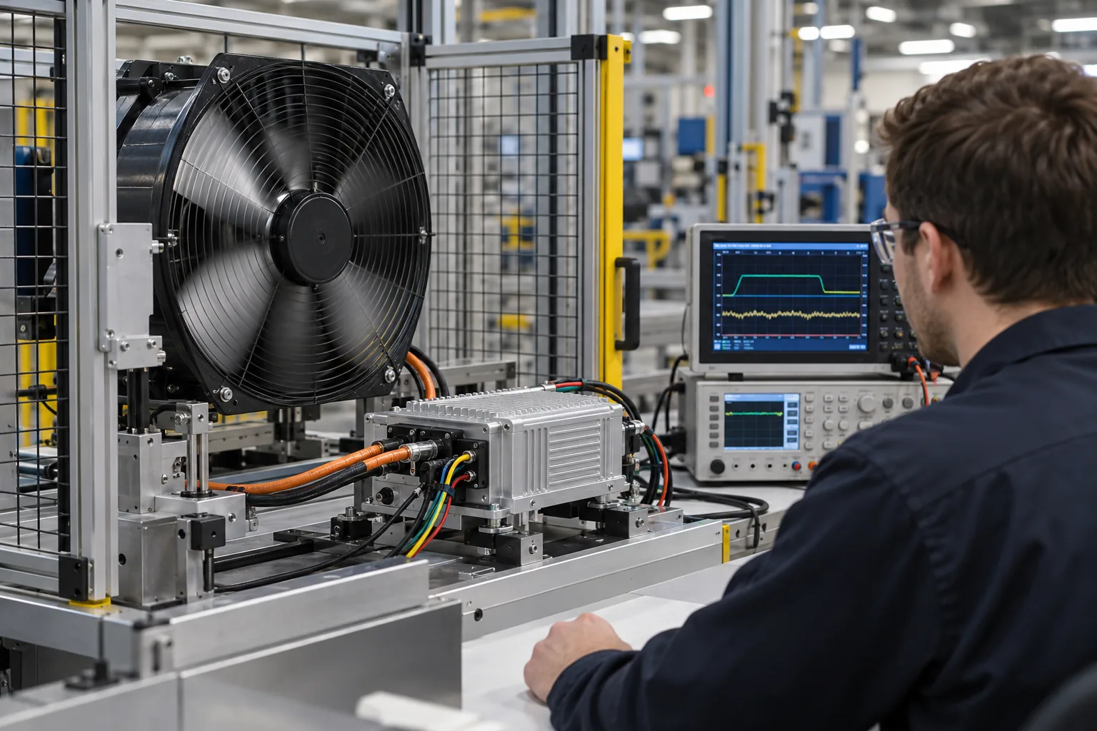
Electrical Verification
Electrical characteristics are evaluated according to the confirmed product or project requirements.
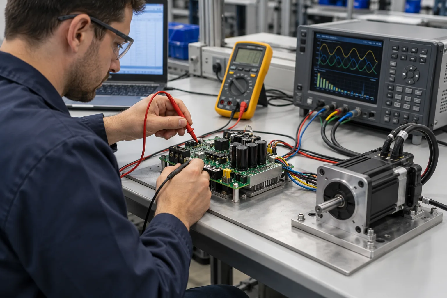
Quality Inspection
Finished products undergo inspection according to defined quality procedures.
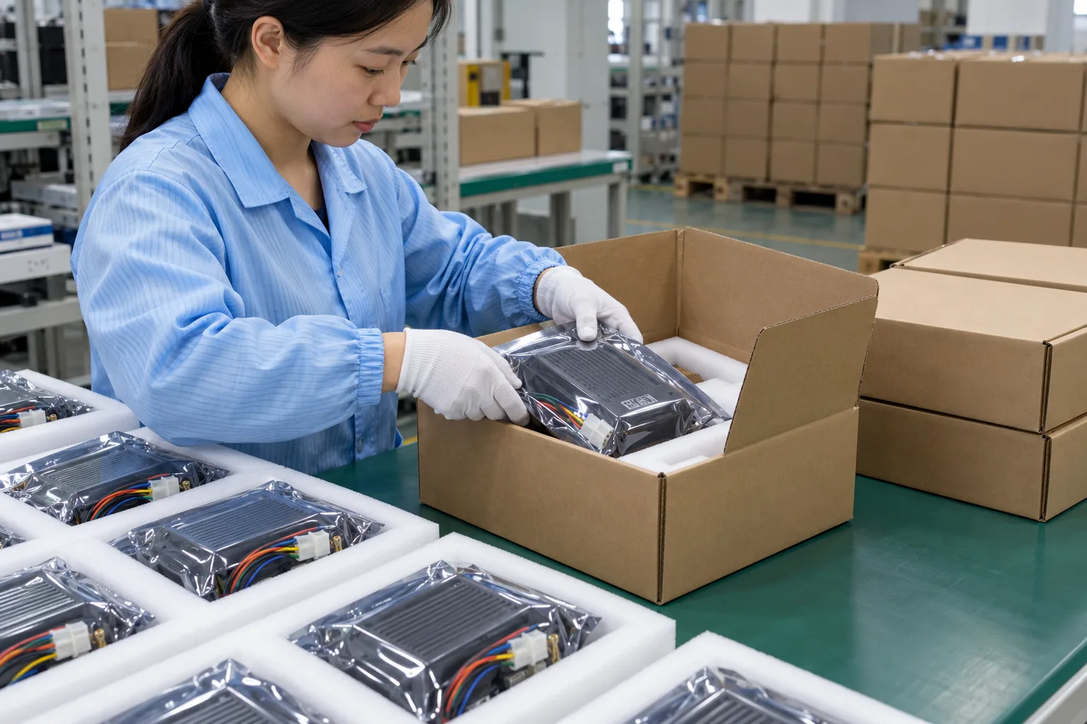
Packaging & Delivery Preparation
Approved controllers are prepared for shipment after production and inspection.
Engineering + Manufacturing Partner
One Development Path From Motor Requirement to Production Controller
VIREOMOTOR combines hardware engineering, software development, motor matching, application customization, prototype evaluation, manufacturing, testing and quality control within one controller-development path.
Engineering Continuity
The same technical requirements can be carried from development into production preparation.
Application-Oriented Development
Evaluate the complete Controller + Motor + Load + Equipment system.
Electrical Customization
Project requirements can include voltage, power, current and other electrical configuration needs.
Control & Software
Control logic, protection functions and communication interfaces can be evaluated by project.
Mechanical + Thermal
PCB structure and thermal management can be part of the customization scope.
Production Implementation
A confirmed custom solution can move into standardized manufacturing and testing processes.