
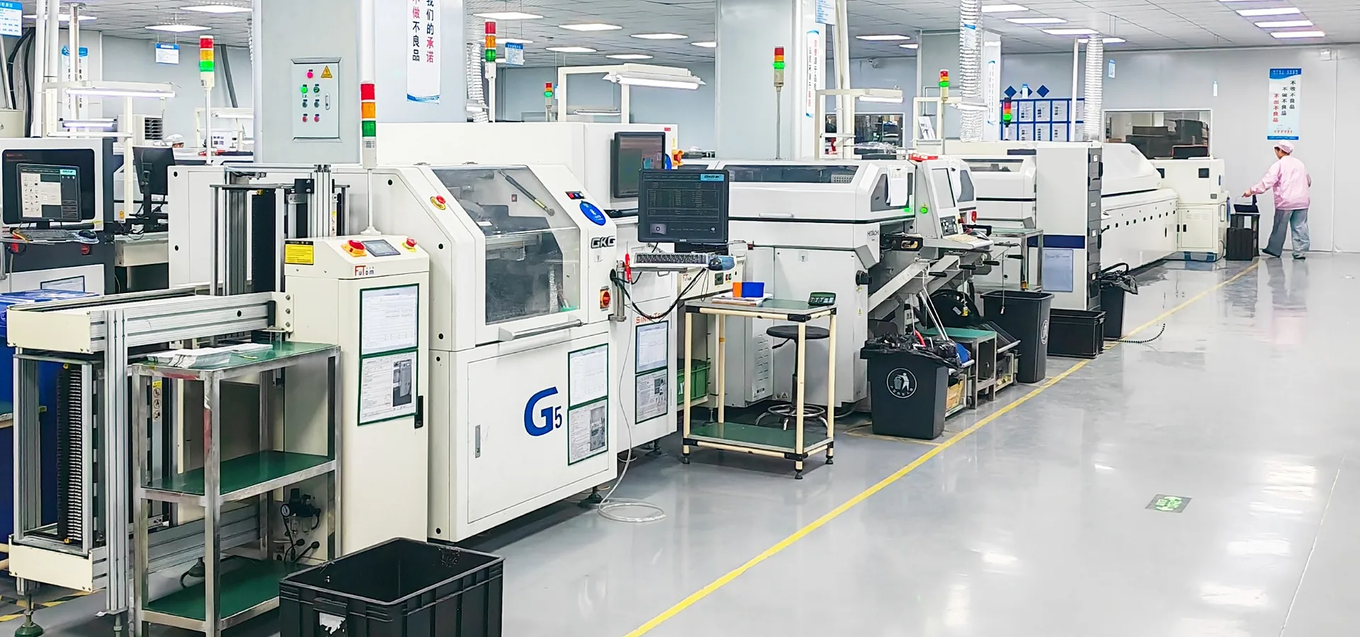
Engineering + Quality
Engineering & Quality for Every BLDC Drive Controller
VIREOMOTOR engineers three-phase BLDC motor drive controllers around the motor, load and equipment requirements. In-house hardware, software, application validation and manufacturing processes support reliable operation from prototype to production.
System-Level Engineering
We Engineer the Controller as Part of the Complete System
A BLDC controller should be engineered as part of the motor, load and equipment system—not as an isolated circuit board.
Hardware, software, electrical configuration and control logic.
Voltage, power, current, speed, torque requirements and motor data.
Real mechanical load and application-specific operating behavior.
Installation, control architecture, duty cycle, cooling and operating environment.
Hardware + Software
Engineering Control From Circuit Design to Motor Behavior
Our in-house R&D team connects circuit design, motor-control software and application requirements.
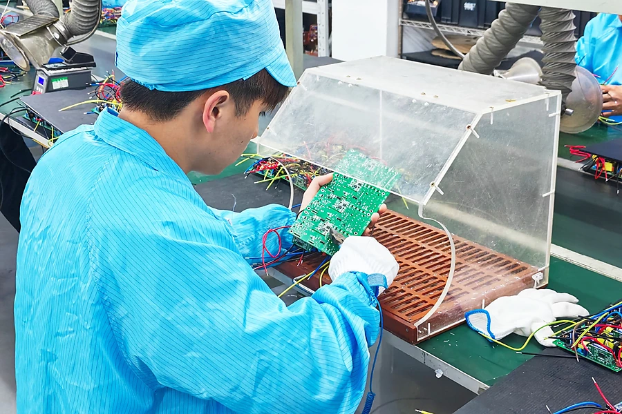
Hardware Engineering
Controller hardware can be evaluated around the electrical, mechanical and thermal requirements of the target application.
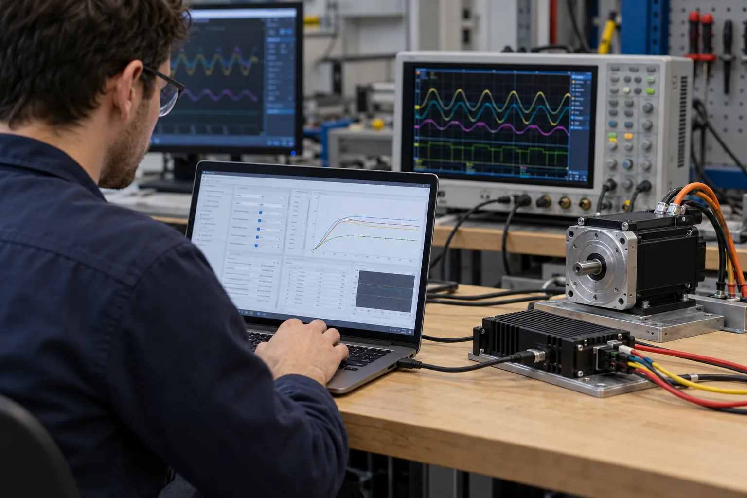
Software Engineering
Software capabilities support evaluation of motor-control behavior, operating logic and application-specific functions.
Application Engineering
Application engineering connects motor behavior, real load conditions and equipment-level requirements.
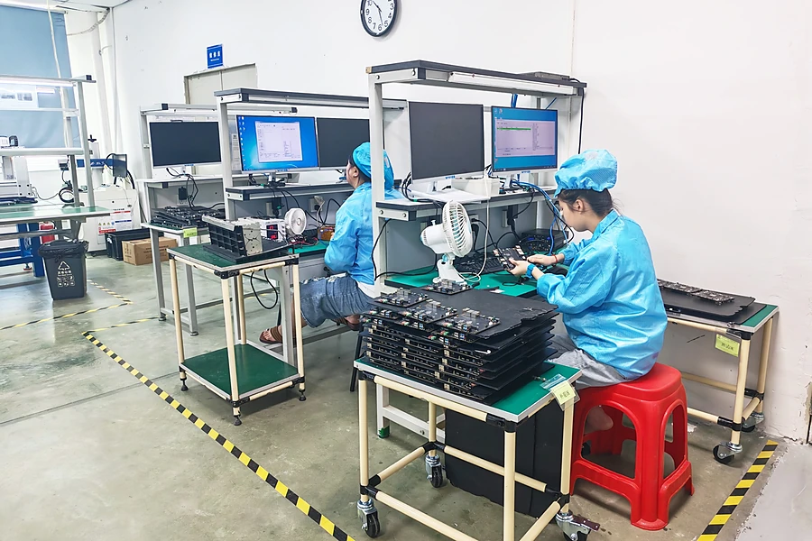
From Requirements to Design
From Motor Requirements to a Validated Controller
A structured process connects motor analysis, controller development, prototyping and validation.
Start by identifying the equipment type, motor application, target operating conditions, control requirements and installation constraints.
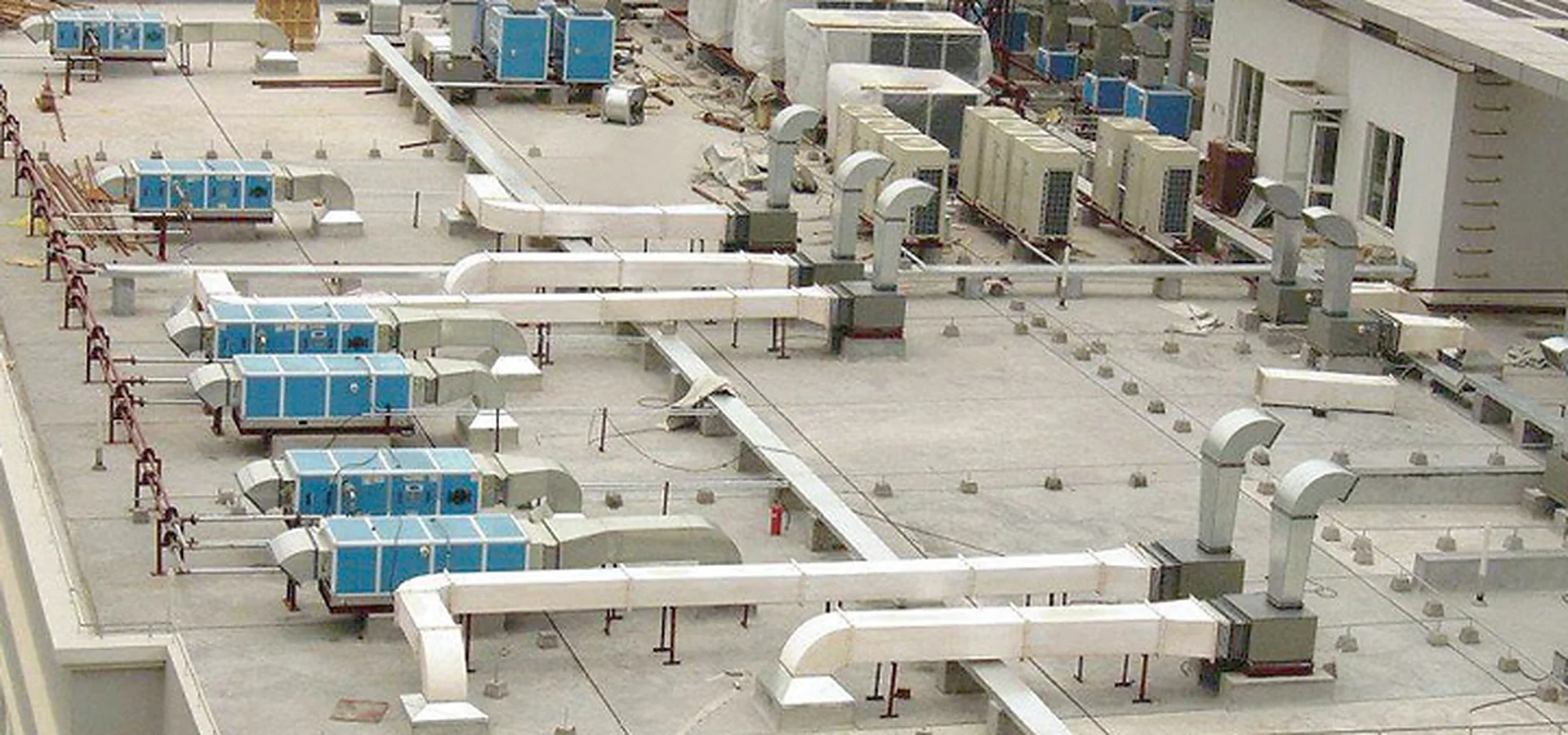
Real Operating Conditions
Different Loads Require Different Engineering Priorities
Motor-control requirements vary by load and equipment. Each controller should match the actual application.
Ventilation Equipment
0.18–5.5 kWAxial fans, negative pressure fans, centrifugal fans, blowers and industrial ventilation systems.
Cooling Fans
15–220 WEnergy storage systems, UPS equipment, power electronics, data center equipment, communication equipment and industrial electronics.
Water Pumps
20–1,000 WIndustrial cooling, water circulation, irrigation, drainage, aquaculture and landscape systems.
Engineering Validation
A Prototype Must Prove More Than Motor Rotation
Prototype evaluation verifies motor behavior, electrical performance, thermal conditions and integration before design confirmation.
Operating Behavior
Startup behavior, running stability, speed regulation, load response and stop behavior.
Electrical Performance
Review controller operation against the confirmed electrical requirements.
Thermal Conditions
Controller heat generation, installation conditions, available cooling and operating duration.
Control Functions
Check control logic against the intended equipment behavior.
Protection & Integration
Check protection functions and integration with the target equipment.
Parameter Optimization
Refine engineering parameters according to evaluation results before design confirmation.
Engineering to Production
Turning Engineering Requirements Into Repeatable Production
Approved controller designs move from engineering validation into standardized manufacturing and inspection.
The approved design defines the production reference.
Manufacturing follows the approved configuration.
Testing and inspection help ensure production consistency.
Hardware Configuration
The confirmed controller hardware is carried into production requirements.
Software Configuration
Where applicable, required software and controller configuration enter the production process.
Component Configuration
Production follows the confirmed controller architecture and component requirements.
Assembly + Functional Requirements
Controllers are assembled to the approved configuration and tested against intended functions.
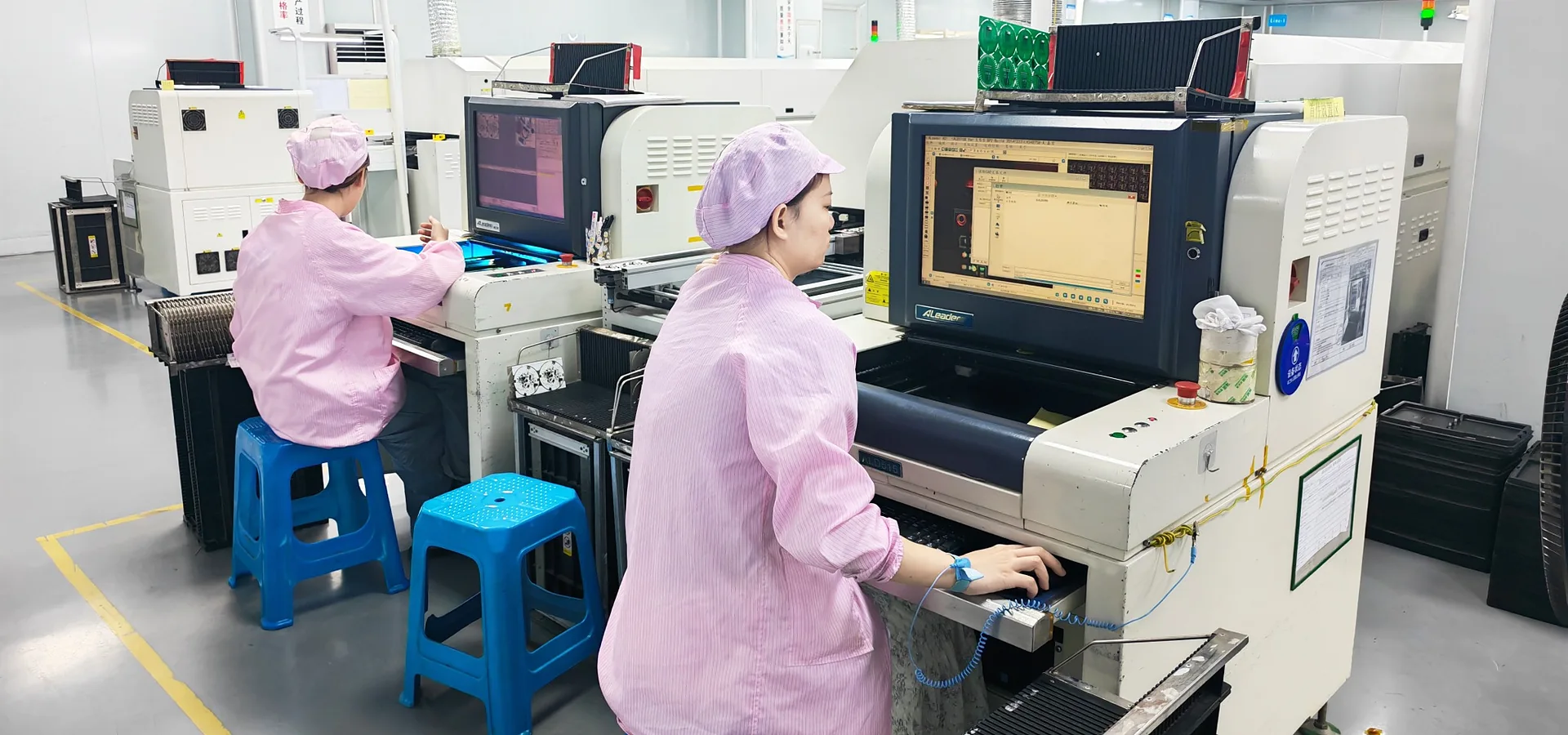
Quality Management
Quality Is a Process, Not Just a Final Inspection
Consistent controller quality depends on controlled design, production, testing and inspection—not only final checks.
Configuration Consistency
Manufacturing should follow the confirmed product or project configuration so that engineering requirements remain aligned with the production controller.
Functional Testing
Controller functions are checked according to the relevant requirements established for the product or project.
Electrical Verification
Electrical operating characteristics are evaluated according to the confirmed controller specification.
Software & Parameter Confirmation
Where applicable, controller software and project-specific parameters can be checked against the required configuration.
Production Inspection
Inspection procedures support identification of manufacturing issues before shipment.
Engineering Feedback
When technical issues are identified during development or production, engineering analysis supports problem evaluation and optimization.
Component Foundation
Quality Begins With Electrical Engineering
Power devices, MCUs and drivers shape controller performance. VIREOMOTOR works with component suppliers on technical solutions.
Power Devices
Evaluation can consider voltage, current, power, application load and thermal requirements.
MCU Solutions
MCUs support motor-control processing, operating logic, signal processing and application functions.
Driver Solutions
Driver components support the controller's power switching and motor-drive architecture.
Thermal Considerations
Component decisions should be evaluated against heat generation, PCB structure, installation and available cooling.
Application Compatibility
Component selection should ultimately support the requirements of the motor and target equipment.
Engineering Continuity
Keep design, validation, production and quality requirements aligned.
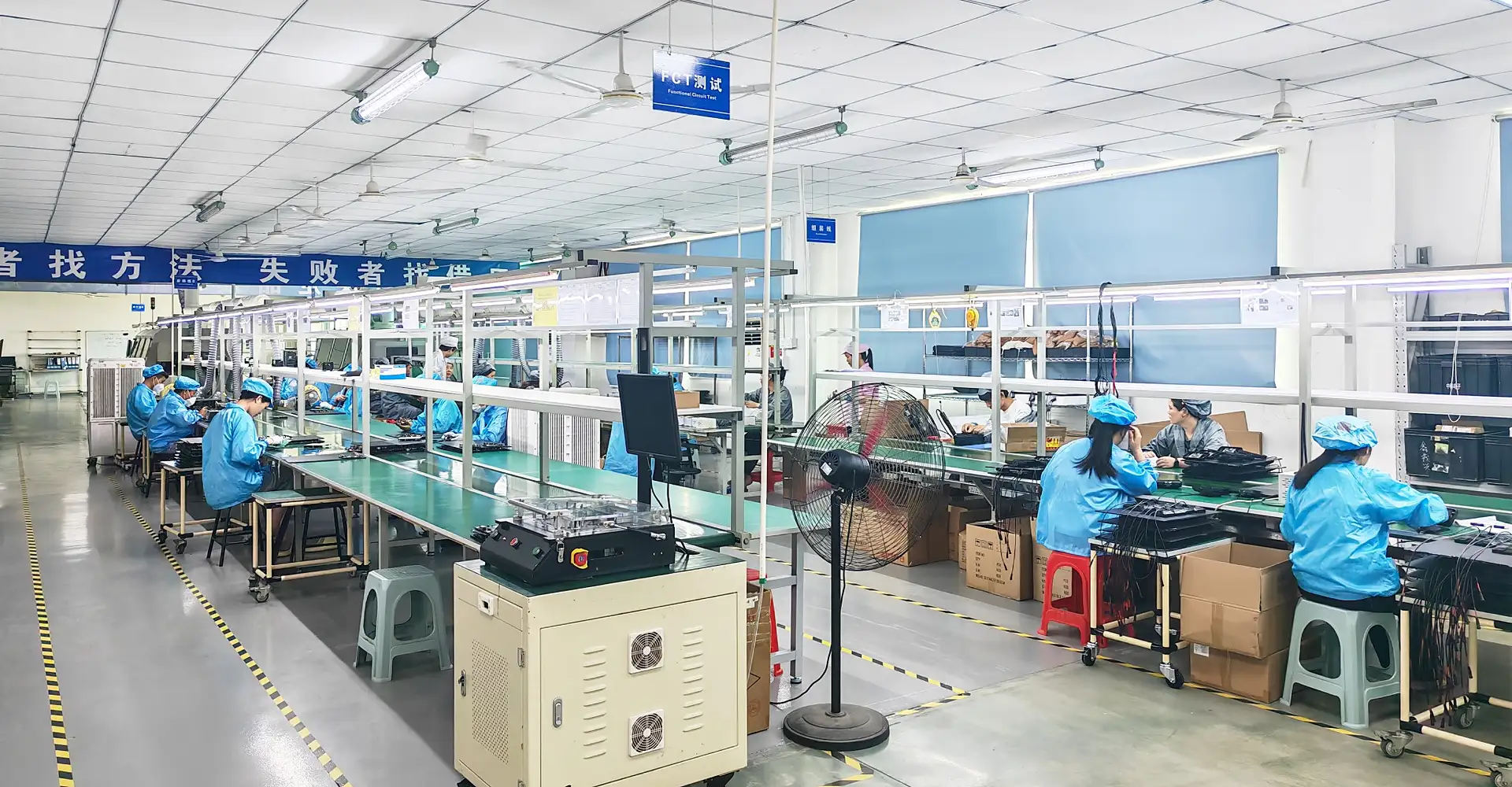
Work With VIREOMOTOR
Discuss Your Engineering & Quality Requirements
Share your motor, equipment and control requirements to help our team assess your project.