
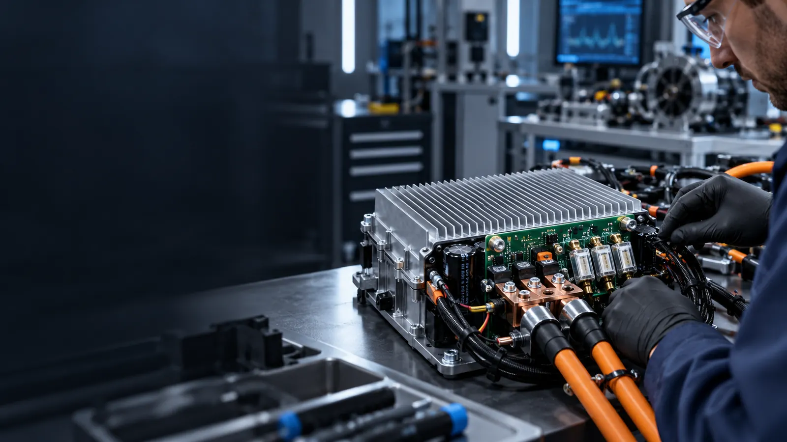
Controller Protection Engineering
Protection Functions Designed Around the Motor and Application
Protection is an important part of BLDC motor controller engineering. A controller needs to operate correctly during normal conditions while also responding appropriately when the motor, electrical system, thermal environment or equipment moves outside the intended operating range.
System Reliability
Protection Is More Than Adding a List of Functions
Different motors and applications operate under different electrical, mechanical and thermal conditions. Protection strategy should therefore be engineered around the actual motor, load, duty cycle and equipment response.
Electrical Conditions Can Change
Power-system behavior and motor loading can create conditions outside normal operation.
Motor Load Can Change
Fans, blowers and pumps can experience different loads during startup and normal operation.
Temperature Can Change
Power, current, structure, airflow, duty cycle and ambient conditions influence controller temperature.
Equipment Response Matters
Fault response should fit the complete equipment operating strategy.
Recovery Is Application-Specific
Different equipment may require different behavior after an abnormal condition.
Protection Architecture
Protection Across Electrical, Motor, Thermal and System Conditions
VIREOMOTOR can evaluate protection requirements across several engineering areas. The exact functions depend on the controller platform and confirmed project requirements.
Electrical Protection Requirements
Engineers can review abnormal electrical conditions that may need to be detected or managed by the controller. The evaluation should reflect the actual motor and equipment architecture.
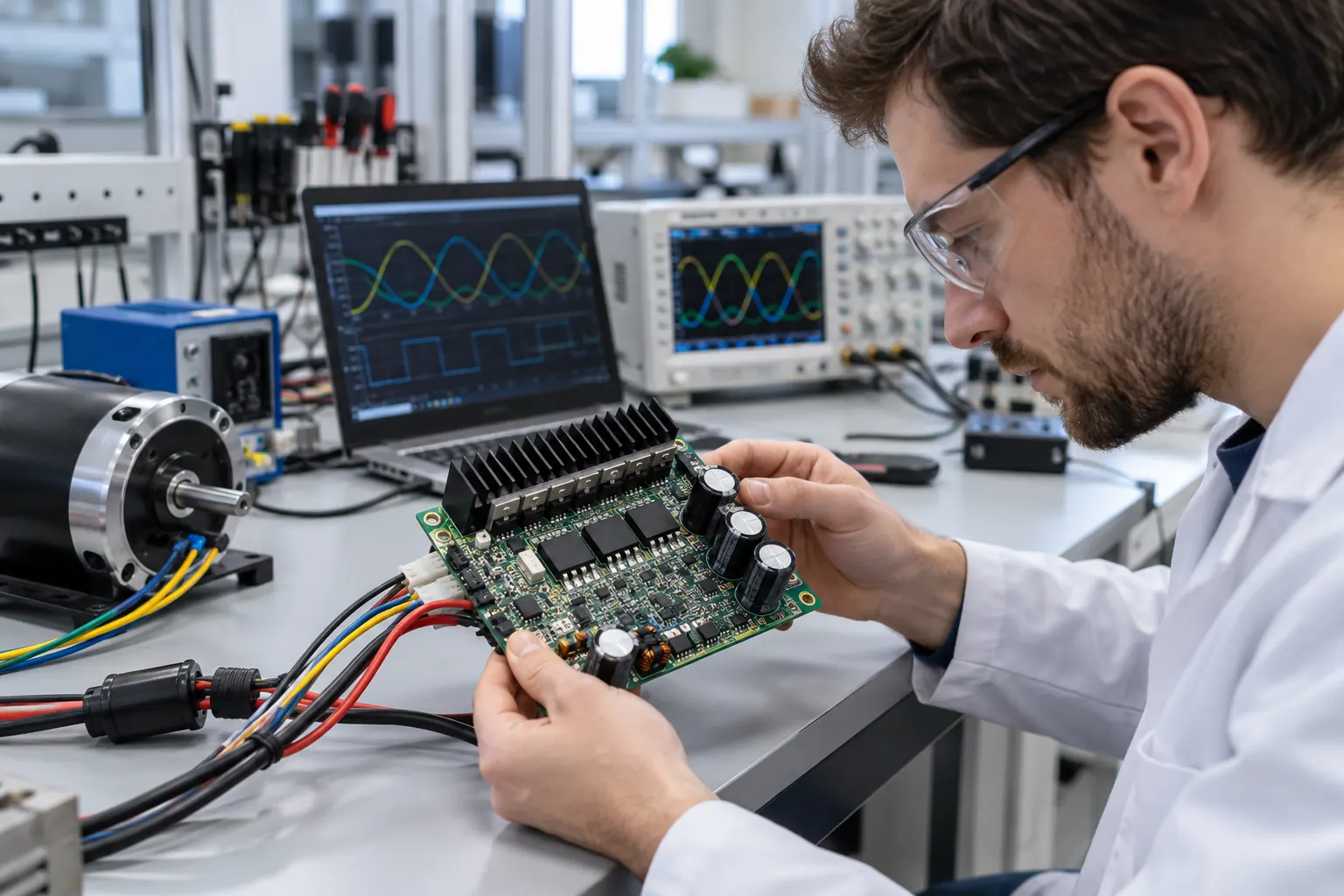
Motor & Load Protection Requirements
The controller may need to distinguish between normal motor behavior and abnormal load conditions. Startup behavior and load variation should be understood before defining the response.
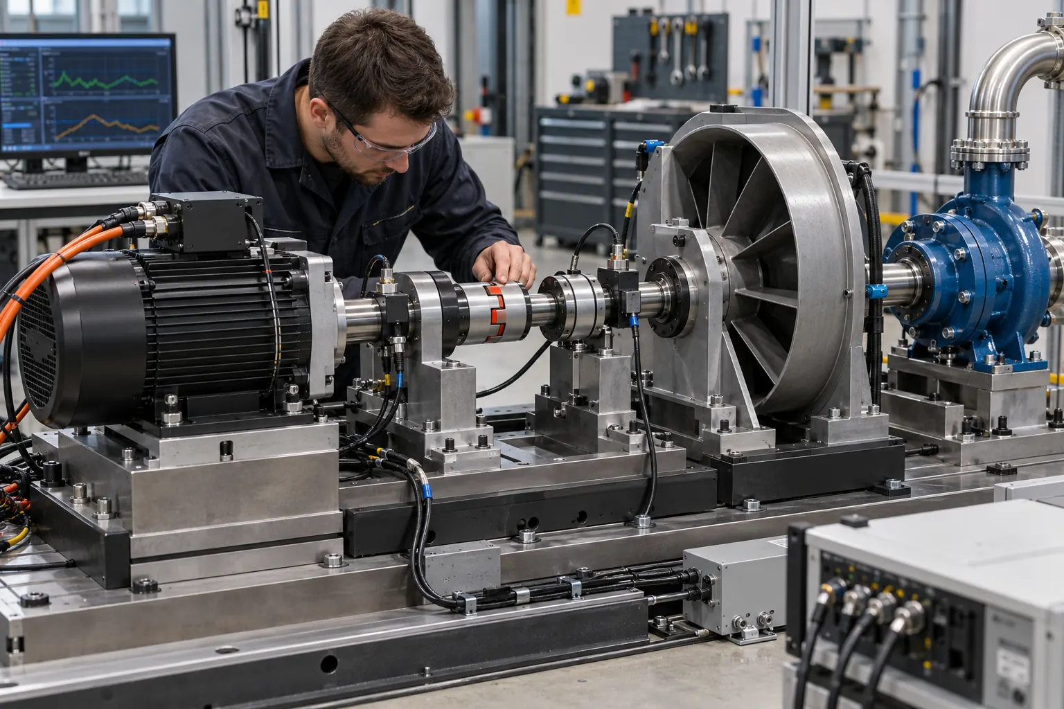
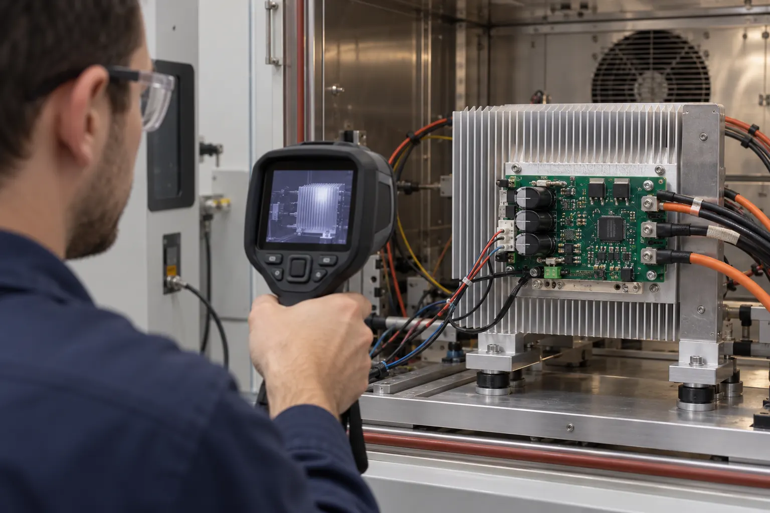
Thermal Protection Requirements
Thermal strategy depends on the electrical load and how the controller is installed and cooled. Long-duration operating conditions should also be considered.
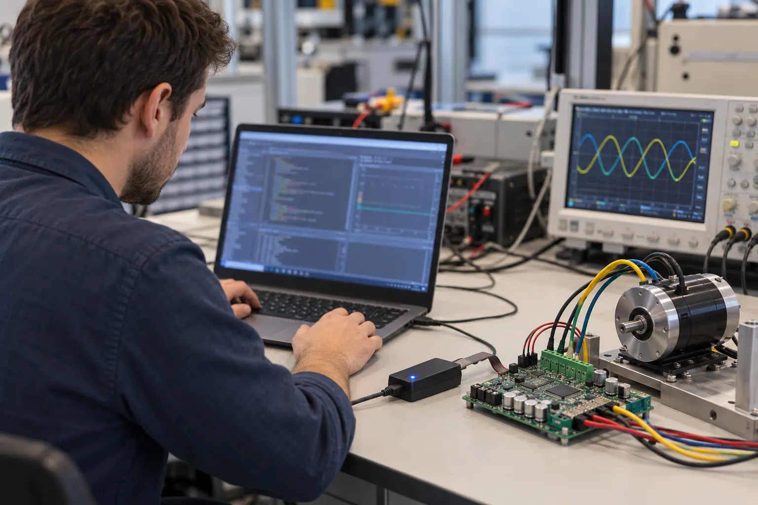
Software-Based Protection Logic
Software can support the detection and handling of defined abnormal conditions according to project requirements. Thresholds and response behavior should be confirmed through engineering evaluation.
Equipment-Level Fault Handling
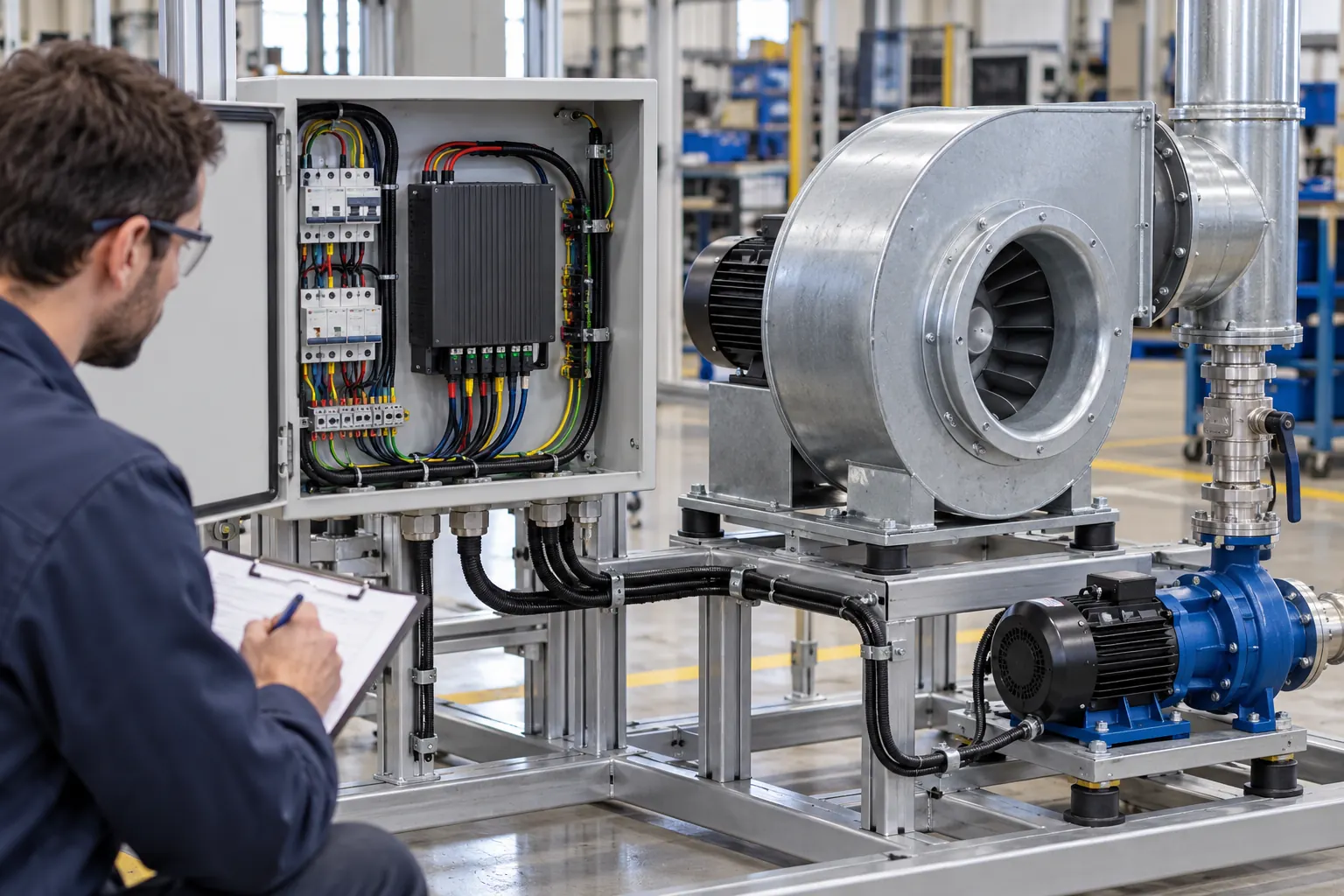
The controller's response may need to coordinate with the equipment's main controller, other electronic modules, operating logic and service requirements.
Application-Specific Protection
Different Loads Require Different Protection Priorities
Protection strategy should reflect how the motor actually operates inside the equipment. Select an application below to prefill the engineering inquiry.
Ventilation Equipment
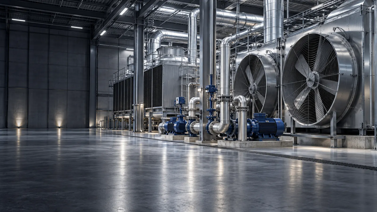
0.18–5.5 kWAxial fans, negative pressure fans, centrifugal fans, blowers and industrial ventilation systems.
Cooling Fans
15–220 WEnergy storage systems, UPS equipment, data centers, communication systems, power electronics and industrial electronics.
Water Pumps
20–1,000 WIndustrial cooling, water circulation, irrigation, drainage, aquaculture and landscape systems.
Engineering Approach
Protection Works Best When Hardware and Software Are Designed Together
Effective motor-controller protection usually requires coordination between controller hardware, sensing, control software and the equipment's overall architecture. VIREOMOTOR maintains in-house hardware and software engineering capabilities to evaluate these areas together.
Power stage, components, PCB design, electrical sensing, thermal design and controller structure.
Condition monitoring, threshold logic, fault states, operating states, recovery logic and coordination.
The final response should coordinate with intended motor behavior and the complete equipment architecture.
Normal vs Abnormal
Protection logic should distinguish intended load behavior from abnormal operating conditions.
Thermal Coordination
Current, power and heat generation are closely related, so electrical and thermal design should be evaluated together.
Motor-Control Coordination
Protection should not unnecessarily interfere with intended motor behavior.
System Coordination
If the controller communicates with another system, fault behavior may need to be integrated into overall equipment logic.
Engineering Process
From Risk Analysis to Confirmed Controller Behavior
VIREOMOTOR follows a structured engineering approach when protection requirements need to be customized. Select a step to review the logic behind the process.
Start by identifying what equipment the motor drives, how the system normally operates, the expected duty cycle, the environment and the important failure conditions.
Engineer-to-Engineer Review
Tell Us What Your Motor and Equipment Need to Be Protected From
For protection-function engineering, the most useful starting point is a clear description of the motor, equipment and abnormal operating conditions you need the controller to manage.
Motor Information
Motor type, voltage, power, current, speed, torque requirements and motor datasheet.
Application Information
Fan, blower, pump or other equipment, plus load, duty cycle, startup and normal operating conditions.
Environmental Information
Working temperature, installation location, cooling conditions, enclosure and available airflow.
Protection Requirements
Important abnormal conditions, expected response, main-system interaction and post-fault behavior.
Existing Design Information
Existing controller specification, current protection logic, wiring diagram and system block diagram.
Fault Information
Fault records and a clear description of the current technical problem when available.
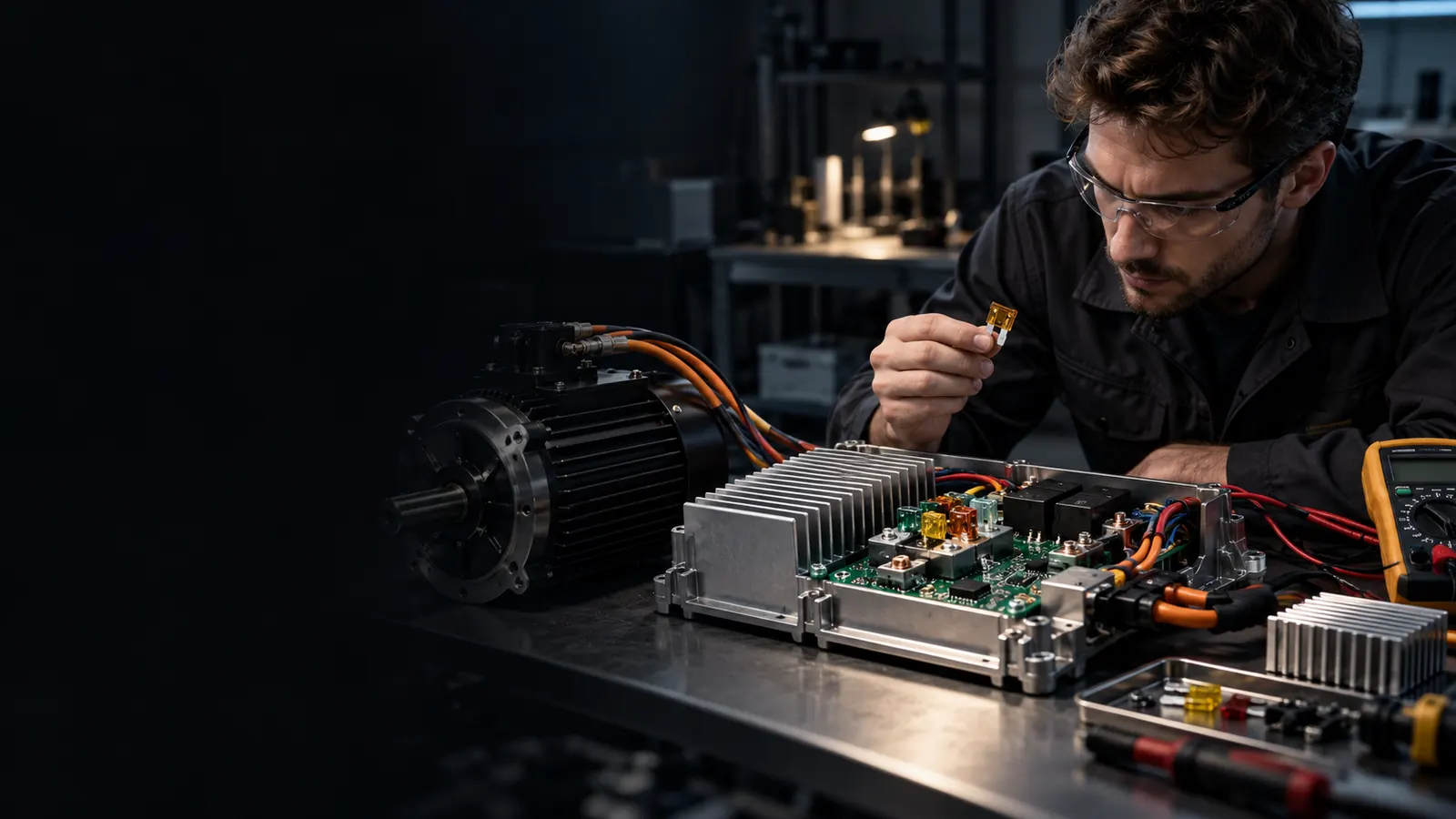
Protection Function Engineering Evaluation
Send Your Protection Requirements
Providing real motor data, operating conditions and fault scenarios helps the engineering team evaluate protection requirements more accurately.