
In-House BLDC Engineering
Hardware and Software Developed Around the Motor and Application
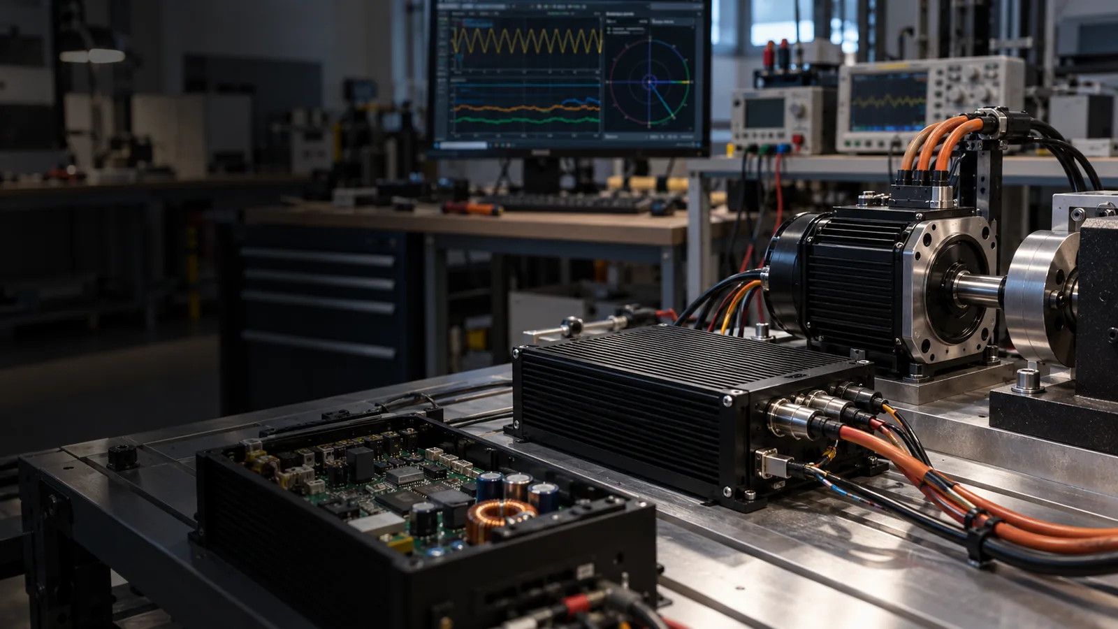
Reliable BLDC motor control requires hardware and software to work as one system. The electrical architecture determines how power is delivered and controlled, while software defines how the motor starts, regulates speed, responds to changing loads and interacts with the equipment.
Controller Hardware
Electrical Architecture Built Around the Motor Requirements
BLDC controller hardware must be matched to the motor, power requirements, installation environment and intended application. VIREOMOTOR evaluates the controller as part of the complete drive system rather than as an isolated PCB.
Electrical Configuration
Motor voltage, rated power, current requirements, load characteristics, startup requirements and operating conditions.
Power-Stage Engineering
Voltage, current, required power, motor load and thermal conditions.
PCB Architecture
Board structure, electrical paths, component arrangement, installation space, connectors and wiring.
Component Selection
Components are evaluated according to the controller architecture and project requirements, including power devices, MCUs and driver solutions.
Protection Architecture
Hardware-level protection requirements can be evaluated according to the motor, equipment and controller design.
Thermal Considerations
Heat generation, available airflow, installation structure, operating duration and equipment temperature.
Control Software
Software Defines How the Motor Behaves
Suitable hardware allows the motor to operate. Suitable control software determines how well it operates inside the final equipment. VIREOMOTOR maintains in-house software-development capability for BLDC motor-control applications.
Motor Startup
Software configuration can be evaluated around motor characteristics, load conditions, desired acceleration and application startup behavior.
Speed Regulation
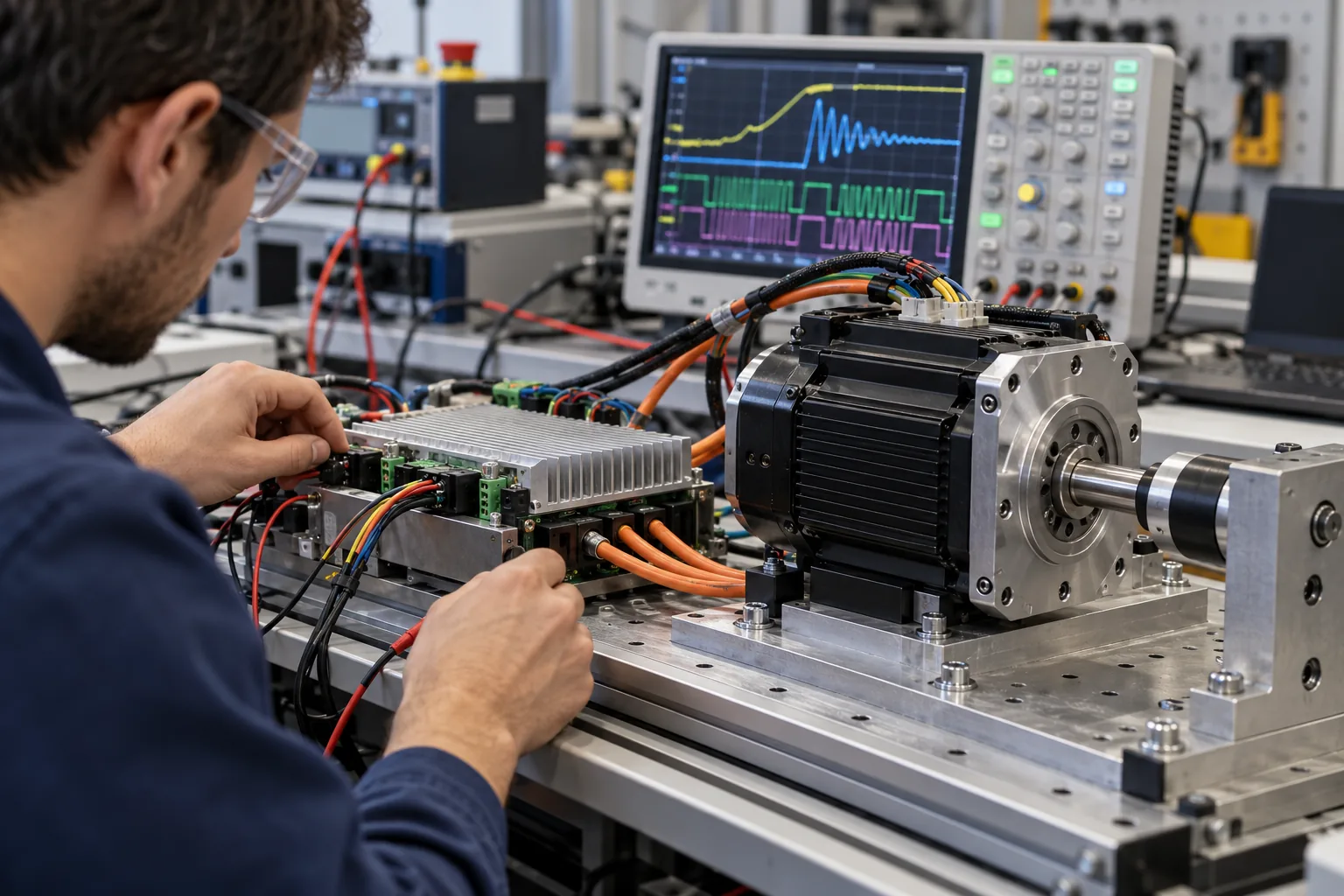
Control parameters can be developed according to rated speed, required speed range, variable-speed operation and load changes.
Operating Logic
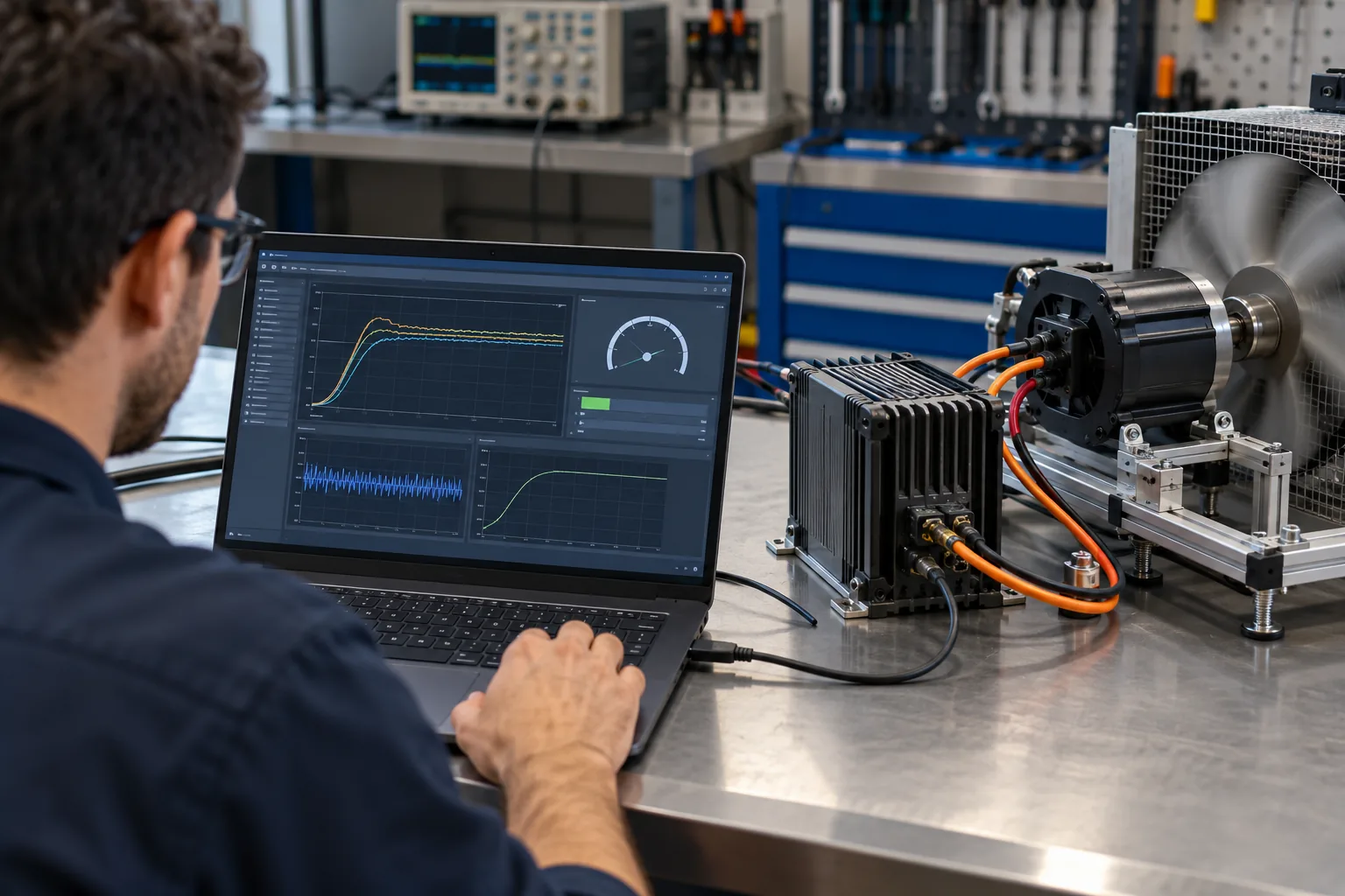
Controller software can support the operating behavior required by the equipment, including different operating states and application-specific control logic.
Load Response
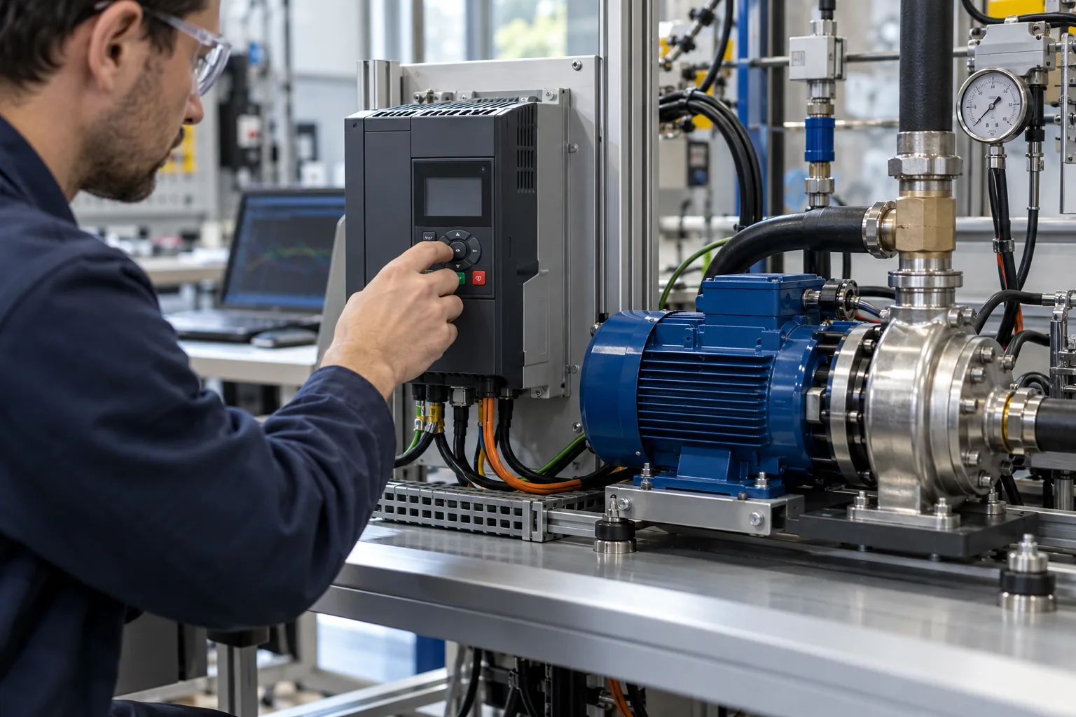
Ventilation fans, cooling fans and water pumps can respond differently to changing loads. Motor-control parameters should therefore reflect the real application.
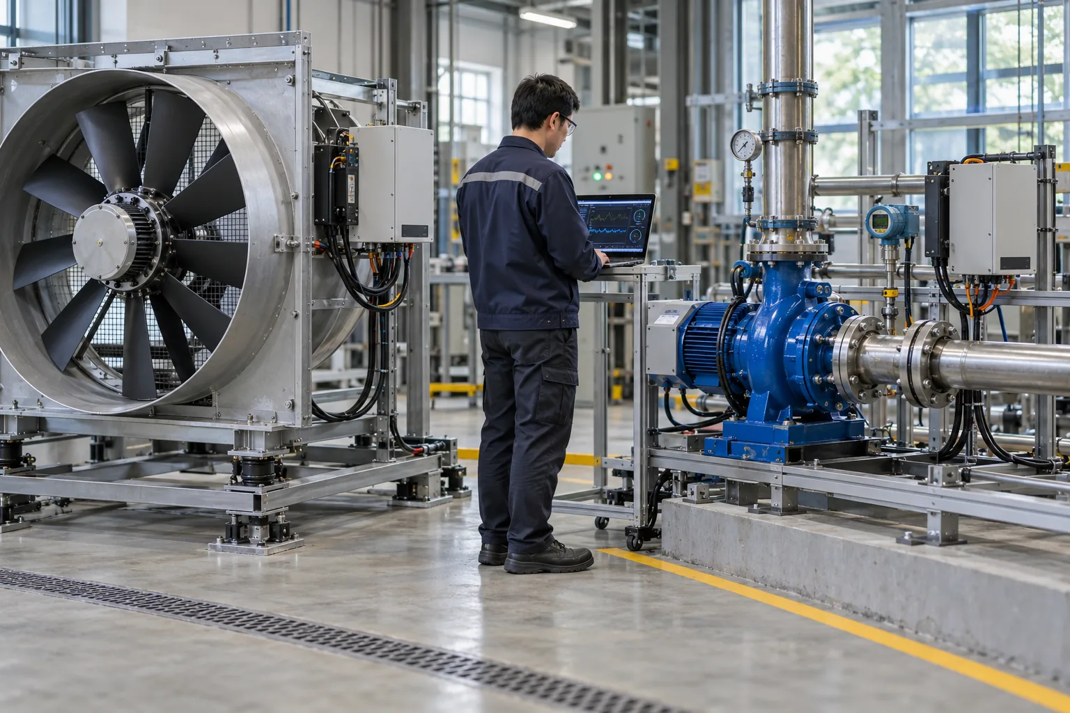
Protection Logic
Software-based protection strategies can be evaluated together with controller hardware and the equipment's operating requirements.
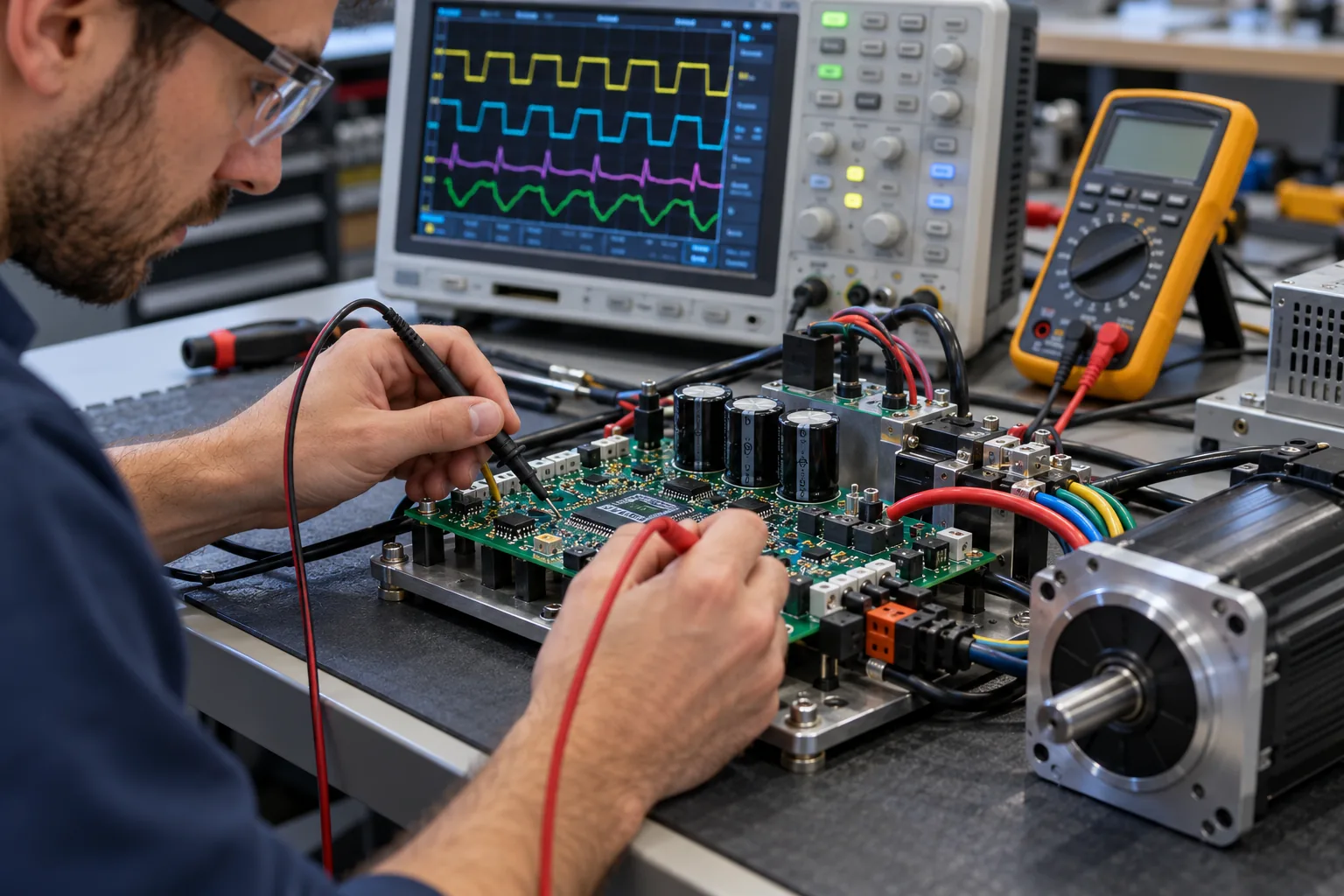
Equipment Integration
Controller behavior can be developed around the requirements of the equipment's main control system where required.
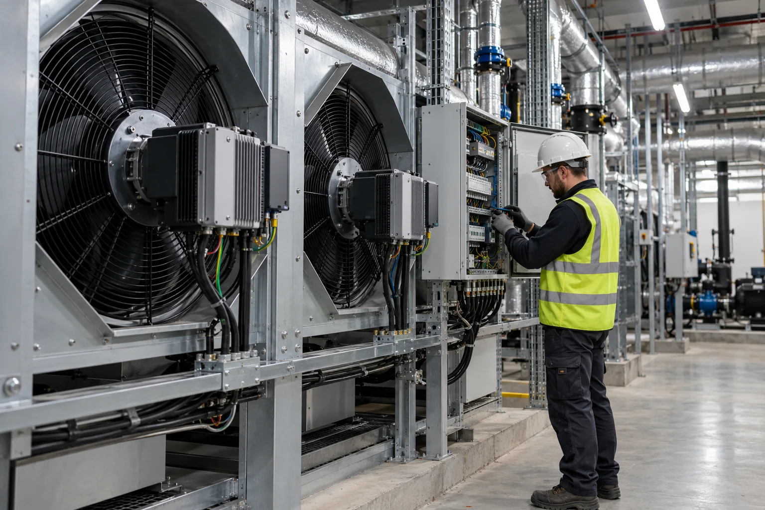
System-Level Engineering
Hardware and Software Must Be Developed as One Controller System
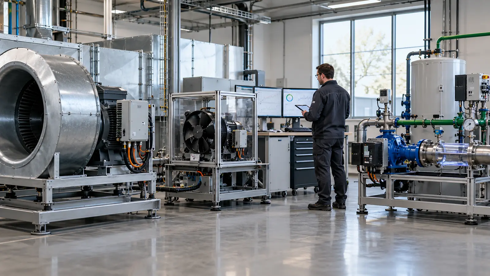
Controller performance is created by the interaction between electrical hardware and control software. Changing one part of the design can affect the other, so VIREOMOTOR evaluates the complete controller system.
Electrical architecture, power stage, PCB and components.
Motor-control parameters, logic and application functions.
Voltage, current, speed, torque requirements and characteristics.
Fan, blower or pump behavior under real operating conditions.
Control architecture, installation, thermal conditions and application requirements.
Electrical + Motor Coordination
Hardware and software are evaluated against voltage, current, speed, torque requirements and motor characteristics.
Control + Load Coordination
The controller should reflect the actual behavior of axial fans, centrifugal fans, cooling fans, blowers or water pumps.
Thermal + Software Coordination
Motor-control strategy can influence electrical loading and controller heat generation.
Equipment-Level Integration
Where required, the controller can be evaluated around interaction with the equipment's main control architecture.
Hardware + Software Protection
Protection strategy may involve both hardware detection and software response.
One Integrated Controller System
Hardware and software should be engineered together rather than treated as separate projects.
Application-Specific Engineering
Different Applications Require Different Hardware and Software Priorities
The same controller architecture is not automatically suitable for every BLDC motor application. VIREOMOTOR adapts engineering priorities according to the motor, load and equipment.
Ventilation Equipment
0.18–5.5 kWAxial fans, negative pressure fans, centrifugal fans, blowers and industrial ventilation equipment.
Cooling Fans
15–220 WEnergy storage systems, UPS equipment, data center equipment, communication equipment, power electronics and industrial electronics.
Water Pumps
20–1,000 WIndustrial cooling, water circulation, irrigation, drainage, aquaculture and landscape systems.
Engineering Validation
Development Continues Until the Controller Works in the Application
The first working controller is not necessarily the final production solution. Where applicable, hardware and software can be evaluated together with the target motor and equipment requirements.
The controller is configured according to the available motor and application information.
Engineering to Manufacturing
Turn a Confirmed Hardware & Software Design Into a Repeatable Product
VIREOMOTOR connects in-house engineering with standardized manufacturing and quality-control processes, helping carry the controller configuration confirmed during development into production.
Hardware Configuration Control
PCB configuration, component requirements, connectors, electrical architecture and product structure.
Software Configuration Control
Where applicable, production requirements can define software version, motor-control configuration and project-specific parameters.
Functional Testing
Controllers can be checked against confirmed operating requirements.
Electrical Verification
Electrical characteristics can be evaluated according to the approved controller or project specification.
Quality Control
Standardized production and quality-management processes support consistency between approved design and manufactured controllers.
Engineering Support
If technical issues are identified during evaluation or production, engineering analysis can support optimization.
Work With the VIREOMOTOR Engineering Team
Start With Complete Motor and Equipment Information
For hardware and software development projects, complete technical information helps engineers evaluate the controller requirements more accurately.
Motor Information
Motor type, rated voltage, rated power, rated current, rated speed, torque requirements and motor datasheet.
Application Information
Fan, blower, cooling fan or water pump; load characteristics, duty cycle and operating environment.
Hardware Requirements
Voltage and power requirements, PCB space, connectors, wiring and thermal conditions.
Software Requirements
Startup behavior, speed requirements, operating logic, protection requirements and equipment integration.