
System Control & Integration
Make the BLDC Controller Work With Your Complete Equipment System
A motor controller does more than supply power to a motor. In modern equipment, the controller may need to respond to commands, regulate motor speed, manage operating states, execute protection logic and exchange information with the equipment's main control system.
Beyond Motor Rotation
The Motor Must Behave the Way the Equipment Requires
A controller can be electrically compatible with a motor and still be unsuitable for the final equipment. Motor behavior is part of the equipment's operating logic, so speed, startup, operating states and system commands must be considered together.
Startup Behavior
Different applications can require different motor startup characteristics.
Speed Regulation
Fixed speed, multiple speeds, continuously variable speed or speed controlled by system demand.
Operating States
Startup, normal operation, load changes, standby, stop and fault conditions may require different responses.
System Commands
The motor controller may receive commands from another electronic control system.
Protection Logic
Protection behavior should be coordinated with the motor and equipment requirements.
Equipment Integration
The controller should operate as part of the complete system rather than independently from it.
Control Customization
Control Strategy Built Around the Application
Depending on the controller platform and project requirements, VIREOMOTOR can evaluate multiple control functions. Exact supported functions should be confirmed for the final controller and project.
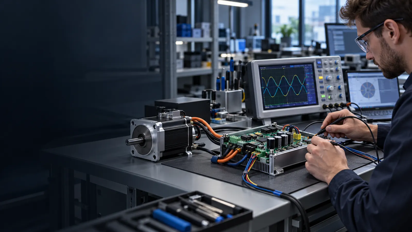
Motor Startup
Controller behavior can be evaluated around the actual motor, application load, required acceleration and startup conditions.
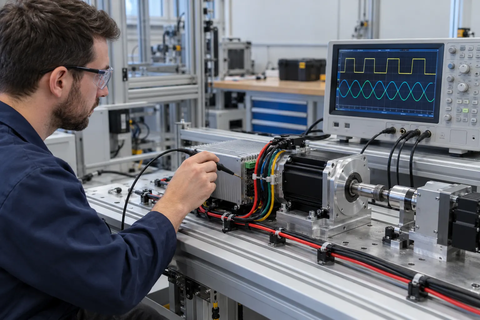
Speed Control
Engineering evaluation can include the required operating speed, speed range, speed transitions and application-specific speed behavior.
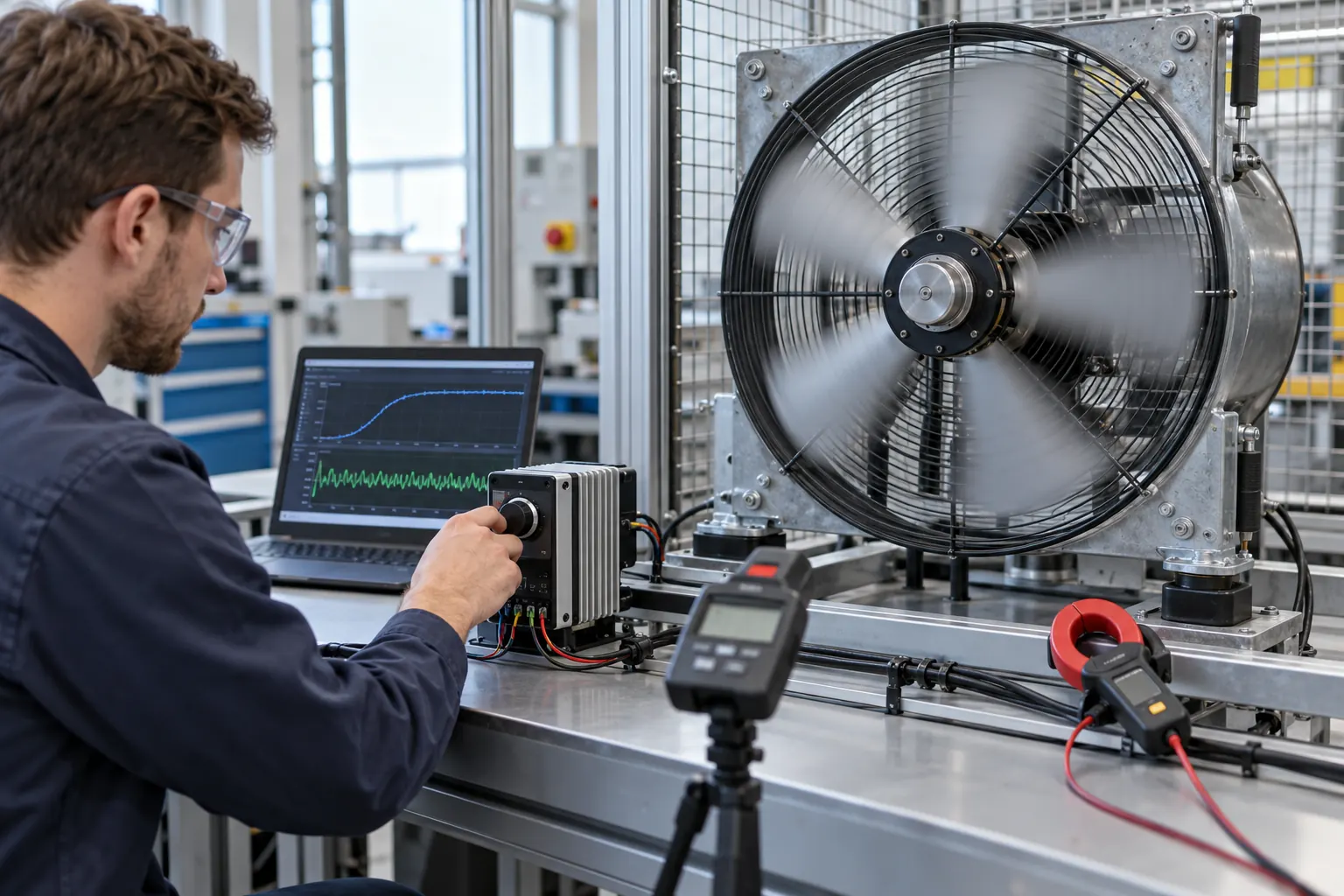
Operating Logic and Stop Behavior
Control software can be evaluated according to the equipment's operating states. Stop response can also be defined according to the application.
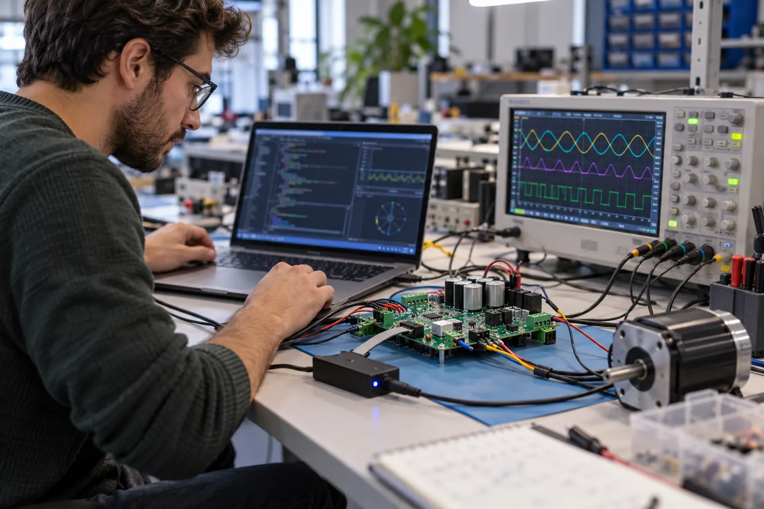
Load Response
Fan and pump loads can change during operation. Control parameters may need to respond appropriately to load changes and equipment demand.
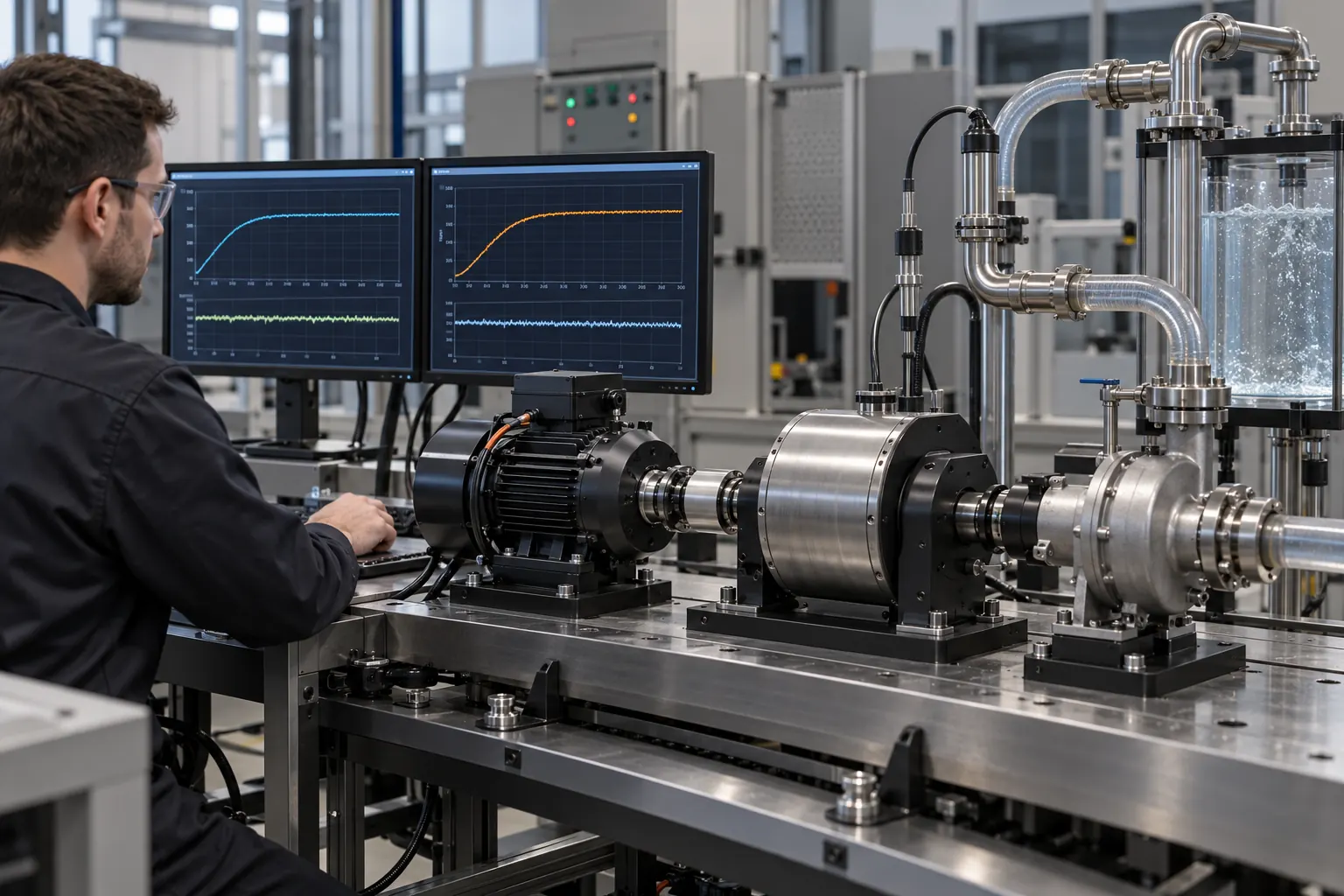
Protection Logic and Application-Specific Functions
Protection requirements can be considered as part of the complete controller strategy. Where technically feasible, operating functions can be adapted to the customer's equipment requirements.
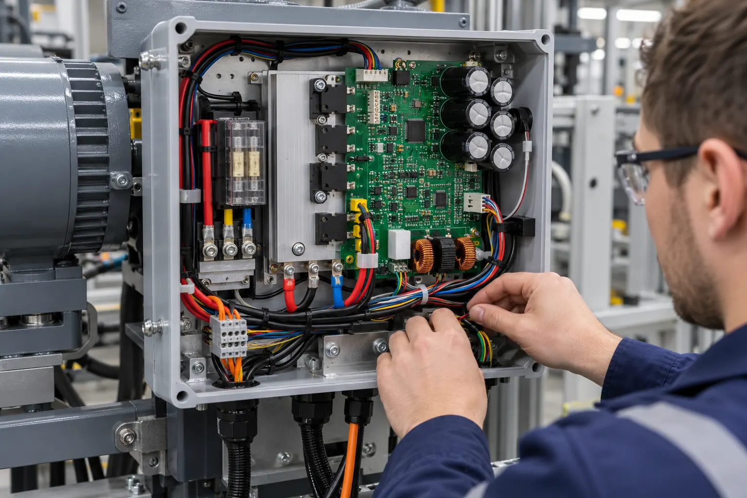

System Communication
Connect the Controller to the Rest of the Equipment
Many OEM systems require the motor controller to exchange commands or operating information with another control system. VIREOMOTOR can evaluate communication requirements as part of controller customization.
Main Controller Integration
Equipment control boards, main system controllers, sensors, user interfaces and other electronic modules.
Command Inputs
Start, stop, speed, operating mode and other application-specific commands.
Operating Feedback
Where required, the system may need operating information from the controller.
Interface Definition
Required interface, electrical requirements, command structure, operating logic and response requirements.
Commands, operating states and system demand.
Control logic, speed regulation, response handling and motor-drive operation.
The final load determines how the motor should behave.
Application Engineering
Different Equipment Requires Different Control Strategies
The control requirements of a ventilation fan, cooling fan and pump can be very different. Select an application below to prefill the project inquiry.
Ventilation Equipment
0.18–5.5 kWAxial fans, negative pressure fans, centrifugal fans, blowers and industrial ventilation equipment.
Cooling Fans
15–220 WEnergy storage systems, UPS equipment, data centers, communication equipment, power electronics and industrial electronics.
Water Pumps
20–1,000 WIndustrial cooling, water circulation, irrigation, drainage, aquaculture and landscape systems.
Engineering Process
From System Requirements to Validated Control Logic
VIREOMOTOR connects application analysis, software engineering, hardware evaluation and production implementation within one development process.
Start by understanding what the motor drives, how the equipment operates and when the motor should start, stop or change speed.
Engineer-to-Engineer Support
Send Us Your Control Logic and System Requirements
The most useful starting point is a clear description of how your equipment needs the motor to operate. Motor data, system architecture and existing communication information help the engineering team evaluate integration more efficiently.
Motor Information
Motor type, rated voltage, power, current, speed and motor datasheet.
Operating Requirements
Startup behavior, speed range, duty cycle, stop behavior, modes and load characteristics.
Control Requirements
How speed should be controlled, commands received, required responses and protection requirements.
Communication Requirements
Required interface, system architecture, main controller information and command or data requirements.
System Files
Motor datasheet, wiring diagram, system block diagram and equipment control-flow diagram.
Existing Specifications
Existing controller specification and communication specification where available.
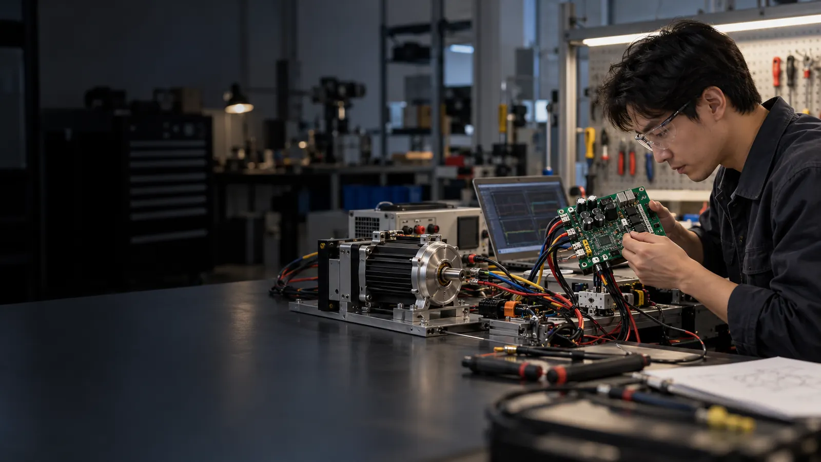
Control & Communication Engineering Evaluation
Send Your Control Requirements
Providing a system diagram and clear operating logic helps the engineering team evaluate controller integration more efficiently.
Control / Communication Inquiry
Get Your Controller Recommendation
Tell us about your motor, equipment and required control or communication functions. Our engineering team will review your information and recommend a suitable BLDC drive controller.